20 21
Таблица 3.1
Meter with a current range The length of the stripped wire, mm Wire cross-section diameter
3
, mm
5(10) А 25
(1÷6)
5(60) А 27
(1÷7)
5(100) А 20
(1÷8)
If it is necessary to incorporate the meter into an AMI system, connect the signal wires to the interface outputs in
accordance with the wiring diagram.
Make sure that the time and date readings of the meter correspond to the actual values, otherwise set the date
and time (for details see САНТ.411152.107-05.1 РП).
Seal the covers and the «ACCESS» button.
Initialize the electronic seal of the clamp cover (see САНТ.411152.107-05.1 РП).
3.4 Wiring diagrams
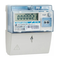
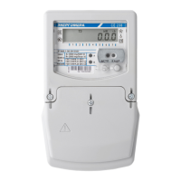
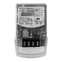
The designation of meter contacts is shown in Figures 3.1-3.2.
ATTENTION! DURING INSTALLATION, FOLLOW THE WIRING DIAGRAM PRINTED ON THE METER PANEL.
3
The range of the wire diameter is specified based on the possibility of its connection to the meter block. The required cross-section
(and therefore the diameter) of the wire is selected depending on the value of the maximum current.


 To Next Page