32 33
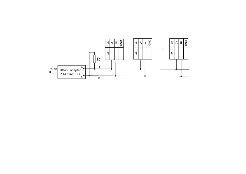
with «A». In order to avoid line overload, activation of biasing resistors with a resistance of 560 Ω, as a rule, is only
performed for the extreme meters.
11
12
13
11
12
13
11
12
13
СЕ308 S31, S34 СЕ308 S31, S34 СЕ308 S31, S34
b) connecting a second additional interface (see Figure 3.1a)
Biasing resistors (+R) and (-R) (nominal 100 kΩ) are installed in the meter and are always connected to the A
and B lines, respectively.
R – termination resistor with a nominal value equal to the cable impedance. GND and GND’ circuits for meters in
S3x bodies are used as required.
Figure 3.6 – Connection diagram of the CE308 meter with a RS485 interface
via RS485/RS232, RS485/USB external adapter to a PC
3.4.4.2 PLC interface connection
For meter versions with a built-in PLC interface (version with P), the data transmission lines from the PLC module