30
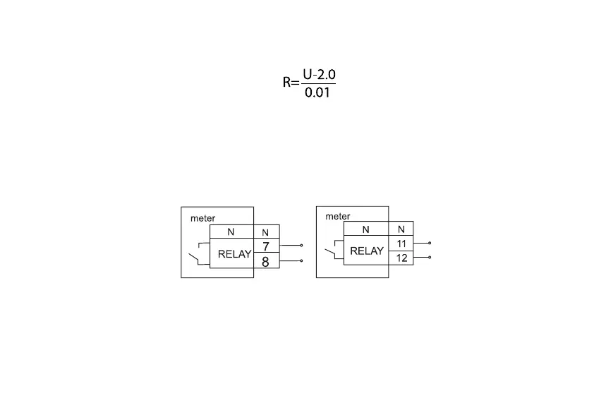
The value of electrical resistance R in the pulse output load circuit is determined by the following formula:
(3.1)
where U is the output power voltage, V.
3.4.2 Relay connection
To implement alarm functions, meter versions with an alarm relay (AR) are provided:
The switching specifications of the relay are shown in Table 2.3, modes of operation – in the
САНТ.411152.107-05.1 РП.
AR connection diagrams are shown in Figure 3.4.
Figure 3.4 – Alarm relay connection diagram
The CE308 S34 meter load control relay provides a break or connection between pins 1 and 3 for phase A, 4 and
6 for phase B, 7 and 9 for phase C (see Figure 3.2d).