12
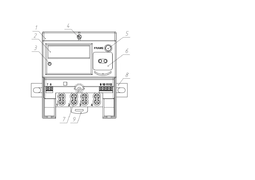
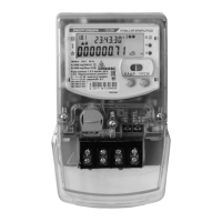
Figure 2.2 – External view and terminals numbering of СЕ102 R5.1
1 – Meter’s cover
2 – LCD
3 – Indicator of power supply and active energy
4, 7 – Sealing screws
5 – «FRAME» button
6 – Optical port
8, 9 – Fixtures
terminal 7 – pulse outputs connection +TM;
terminal 8 – pulse outputs connection -TM;
terminal 9* – EIA-485 interface «А» terminal;
terminal 10* – EIA-485 interface «B» terminal;
terminal 11* – «-» EIA-485 interface power supply;
terminal 12* – «+» EIA-485 interface power supply.
* – for modifications with EIA-485 interface