3
5.0 INSTALLATION
Electric Motors Only
Note: Electrical connections should be made only by a
qualified electrician, adhering to all applicable local
and national codes.
1. Wiring — Make sure all power has been turned off.
Remove the cover from the magnetic starter switch.
Observe the diagrams on the inside cover of the starter
switch box for the correct wiring instructions and
connections. The 230V, 460V and 575V models differ
in the safety overload heaters and the wiring scheme.
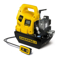
2. Solenoid Valve Pendant (PER Models) — Attach
the pendant (see Fig. 8) to the solenoid valve using
the connector. Plug valve power cord into 115 VAC
outlet.
All Gasoline and Electric Models
3. Vent Plug — Turn the oil fill cap counterclockwise
one-quarter turn to vent reservoir. Failure to do so
will cause cavitation and damage to the pumping
mechanism may result.
4. Attaching Hoses — Thread hose(s) into 3/8” NPT
outlet port(s) of the valve, as shown in Fig. 1, “A.”
Use 1 1/2 wraps of Teflon tape on the hose fitting,
leaving the first thread completely free of tape, as
shown in Fig. 2, “B.” Pumps with 3-way valves have
one outlet port, and pumps with 4-way valves have
two outlet ports. All hoses and components used
with this pump must have a working pressure rating
higher than, or equal to, the maximum pressure
rating of the pump (10,000 psi).
Figure 1
Figure 2
B
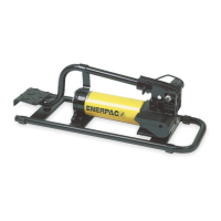
5. Oil Level — Check the
oil level of the pump
prior to start-up, and
add Enerpac hydraulic
oil, if necessary. Oil
level should be at the
top of the sight gauge,
and should never fall
below visible level. If
it does, pump damage
may occur (see Fig. 3).
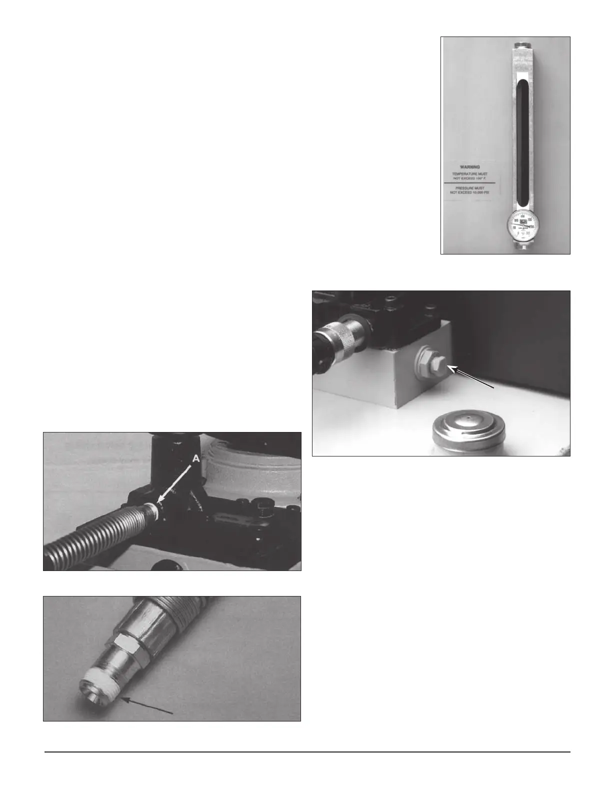
6. Return-to-tank port
— A 3/8” NPT port is
provided on side of
valve mounting block,
as shown in Figure 4,
for connecting tank
lines from remote
valves.
NPT Port
Figure 4, Valve Mounting Block
6.0 OPERATION
1. Check oil level of pump and add oil if required. Make
sure the pump reservoir is vented. (See 5.0 Installation,
step 5).
2. Shift manual valves to the neutral position before
starting pump. If equipped with an electric valve,
when neither the advance or retract buttons are
pushed, valve is in the neutral position. (See step 5,
Valve Operations.)
Electric Motors
3. The power switch is located on the starter box on the
side of electric motor. When initially starting electric
models, it may be necessary to jog the motor by
pushing the start and stop buttons quickly several
times to prime the piston pump.
Gasoline Engines
4. Fill fuel tank with regular unleaded gasoline. Replace
fuel cap and wipe any spilled gasoline from engine
and fuel tank. Check engine oil level and add/fill as
required.
Figure 3, Sight Gauge
 Loading...