a) fit the inner-shield to the module.
b) bolt the terminal plate insulating bracket to the frame of the steel module.
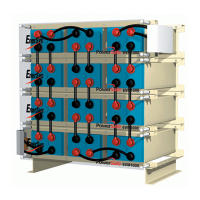
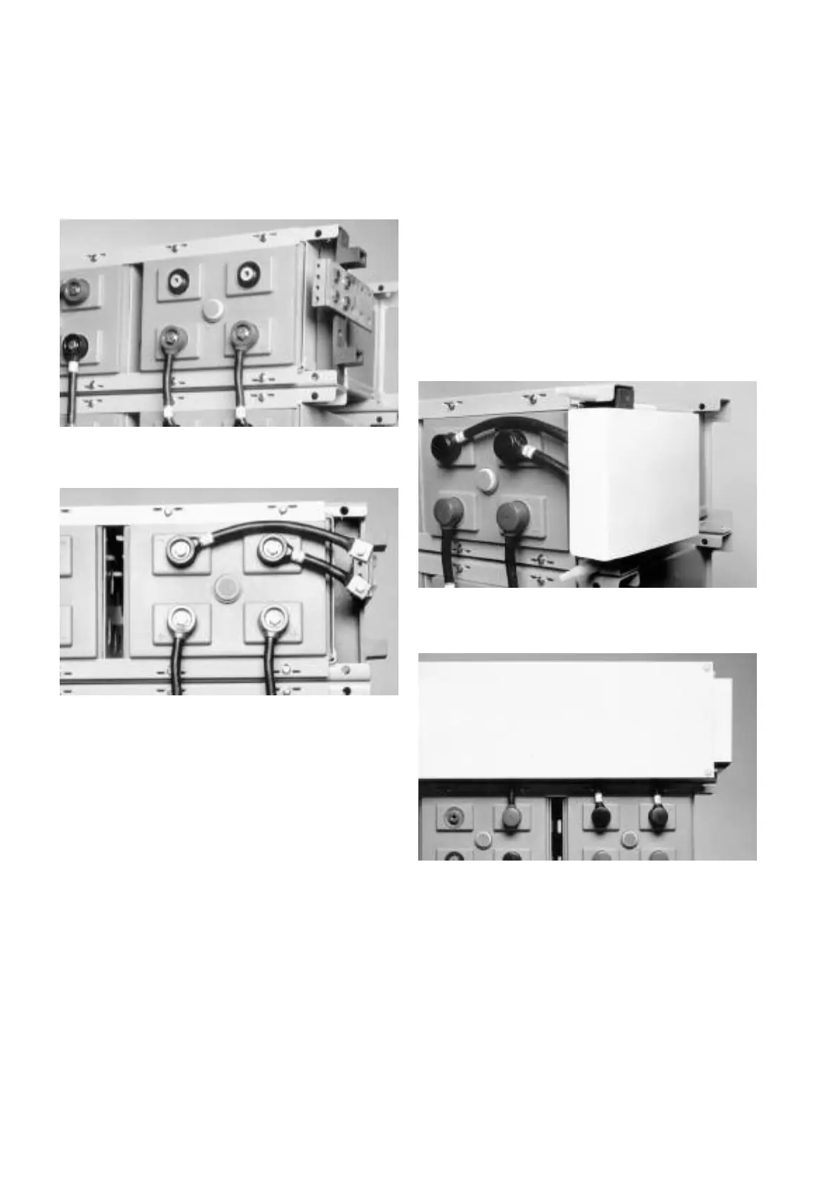
c) bolt the main terminal bracket and terminal plate to the mounting bracket,
see Fig 7.
d) fit the take-off connector(s) between the cell terminal(s) and the main
terminal plate, see Fig 8.
e) where cable connectors are used, fit the insulating lids to each of the
terminals.
9. Final Assembly Connections, Checks and
Commissioning Charge
a) in order to identify each cell within the battery, a set of self adhesive
numbered labels are supplied for fixing to the cell lids.
It is normal practice to identify the positive end cell as No.1 with the
remaining cells being numbered consecutively following the path of the
electrical connections throughout the battery.
b) once all the connections have been tightened to the correct torque and
with the battery on open circuit, read and record the individual cell and the
total battery voltage using a DC voltmeter. The total battery voltage should
be approximately equal to the number of cells multiplied by the reading of
one cell. If it is less, re-check the connections for the correct polarity.
c) fit the four support rods (see illustration Fig 6) to each of the module
frames.
The assembly of the battery is now completed to the stage where external
electrical connections can be made to commence the Commissioning Charge.
The connections between the battery and it’s associated charger are made at
the main terminal plates. Ensure that the charger POSITIVE lead is connected
TO the main battery POSITIVE terminal and that the charger NEGATIVE lead is
connected TO the main battery NEGATIVE terminal. Care should be taken in
selecting the size of these connecting cables to optimise the voltage drop
between the charger output terminals and the main battery terminals.
Where battery strings are to be connected in parallel, this voltage drop should
be equalised in each of the circuits to avoid imbalances in the
charging/discharging circuits of the different strings which may result in
damage to the battery system and a reduction in operating life.
Once these connections have been made:
d) attach the outer shield to both the positive and negative main terminal
take-offs, see Fig 9.
e) attach a front panel to the four support rods on each of the modules with
the connector sheaths provided, see Fig 10.
f) with NO LOAD attached to the system, switch on the charger and record
readings of cell voltage and charge current to form the very important
Commissioning Charge Record for future reference. It is intended that the
example Battery Record Sheet shown on page 12 of this manual be
photocopied and used for recording purposes.
g) continue the charge until the current flow into the battery has fallen to a
minimum and remained constant for 3 consecutive hourly readings.
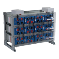
Figure 9: Outer shield attached to the main terminal take-offs
Figure 10: Front panel attached to the four support rods
Figure 8: Take-off connectors between cell terminal and main terminal plate
Figure 7: Main terminal bracket and terminal plate bolted to the mounting bracket
6