i) repeat E, F and G.
j) attach the two lifting strap/hook assemblies provided to the module and
using the lifting device position the module on top of the first and bolt
them together using the hardware provided.
k) repeat D, E etc. until the modules have been fully assembled as shown on
the assembly drawing. Carry out a final check to ensure that the modules
are correctly orientated with respect to polarity.
l) discard the lifting strap/hooks - they are not intended for long term use.
8. Electrical Connections
8.1 Inter-tier and inter-row Connections.
a) before despatch from the factory each individual cell terminal is cleaned
and coated with a layer of non-oxide grease.
b) all the cell terminals have their polarity clearly marked by either a RED ring
to denote a positive terminal or a BLACK ring to denote a negative
terminal.
c) the connector contact surfaces should be cleaned and a thin layer
of non-oxide grease applied.
d) taking note of the polarity fit all the inter-tier and inter-row connectors as
shown on the battery assembly drawing using the hardware provided.
Tighten them in accordance with the torque limit information in Appendix
“B”.
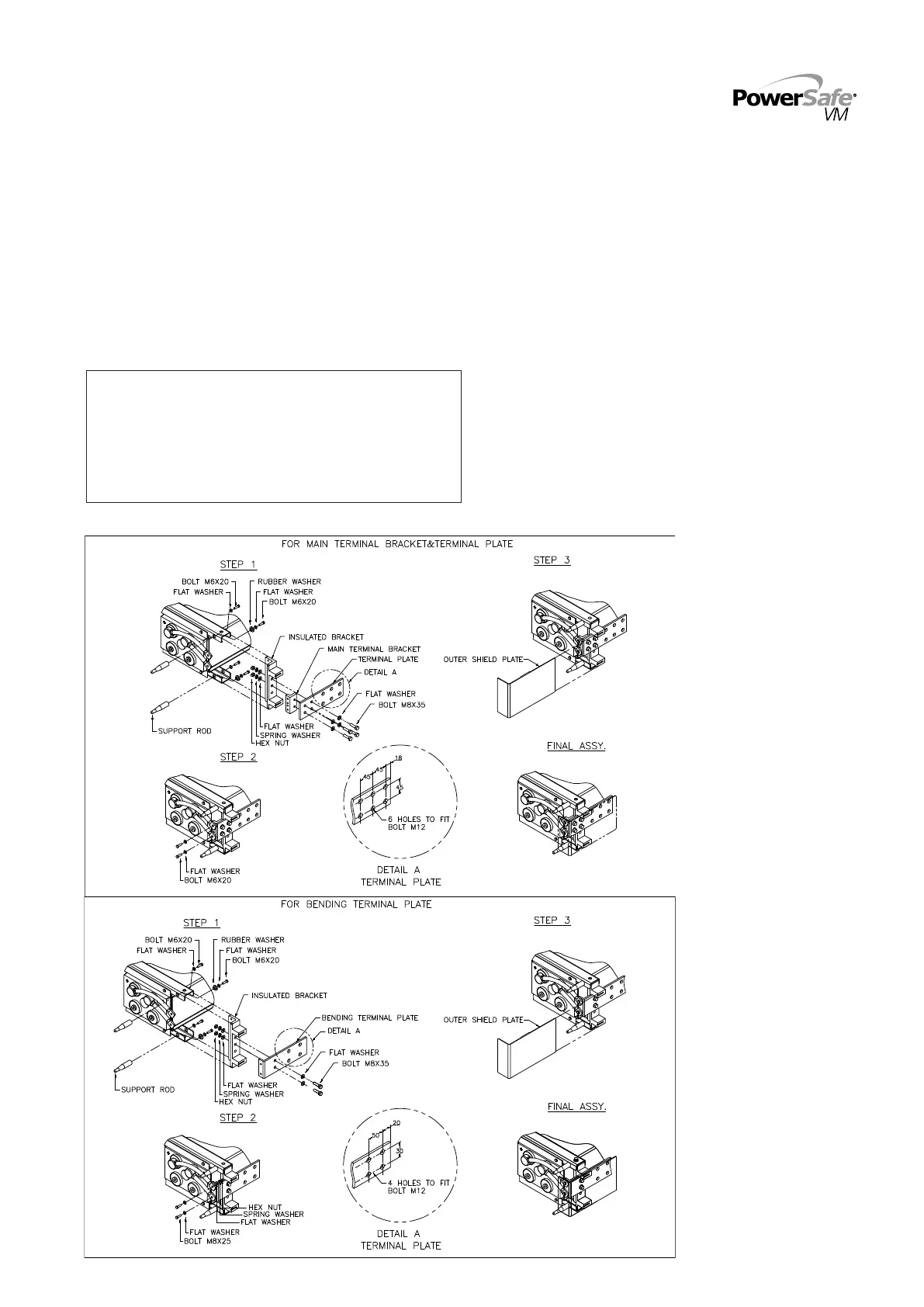
8.2 Terminal Assembly
Figure 6a
: Main terminal assembly detail
WARNING -
BEFORE YOU START WORK - MAKE CERTAIN YOU ARE FAMILIAR WITH
THE POLARITY SEQUENCE OF THE CONNECTIONS. SOME SYSTEMS
MAY BE CONNECTED SO THAT THE CELL CASE AND/OR THE RACK ARE
LIVE RELATIVE TO THE TERMINALS.
INADVERTANT SHORT-CIRCUIT BETWEEN THE TERMINALS AND
BATTERY CASE WITH A METAL OBJECT SUCH AS A CONNECTOR OR
TOOL COULD CAUSE SERIOUS INJURY OR DEATH.
5
Figure 6b: Bending terminal assembly detail