7. Unpacking and Module Assembly
A typical battery installation will comprise one case of accessories and a
number of associated cases each containing two modules. Throughout the
installation procedure the correct hardware may be selected in consultation
with the assembly drawing and the correct torque value from Appendix “B”.
a) remove the lid of the battery accessories case and take out the different
item packs, see Fig 1. Consult the battery assembly drawing to become
familiar with the different accessory items and the polarity orientation of
the finally assembled modules.
b) using the assembly drawing, the tape measure and the chalk line, mark the
intended position of the battery on the floor.
c) take the mounting base channels, place them in position and when
required anchor them to the floor. NOTE - it is the responsibility of the
installer to comply with the relevant building codes and local regulations
and to provide the appropriate anchoring materials.
d) remove the lid and four sides from a case of modules. Note that for
security during transportation the two modules are bolted both together
AND to the base pallet of the packing case, see Fig 2. Remove all the
transit bolts to allow the modules to be lifted clear of the pallet base and
onto the floor.
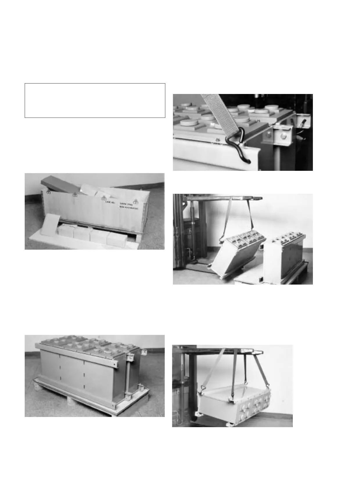
e) take one of the two lifting strap/hook assemblies provided and attach it to
a module. DO NOT USE THE HOLE IN THE SHORT SIDE OF THE U
CHANNEL - USE ONLY THE HOLE DEPICTED IN FIG 3 .
f) using the lifting device raise the module just clear of the pallet,
see Fig 4 and place it vertically on the floor.
g) taking note of the polarity orientation of the module again use one of the
lifting strap/hook assemblies and the lifting device to lay the module
horizontally on the floor.
h) attach the two lifting strap/hook assemblies provided to the module, see
Fig 5, and using the lifting device position the module onto the mounting
base channels. Use of the locating rod may simplify the alignment of the
holes. Bolt the module to the base channels using the hardware provided.
Figure 5: Positioning the module onto the base channels
Figure 3: Lifting strap/hook attached to a module
Figure 4: Lifting the module clear of the pallet
Figure 2: The modules bolted together and to the pallet using transit bolts
Figure 1: Battery accessories case
WARNING -
THESE BATTERIES ARE HEAVY. SERIOUS INJURY COULD RESULT
FROM MISHANDLING. DO NOT ATTEMPT TO LIFT THEM WITHOUT
MECHANICAL ASSISTANCE.
DO NOT WORK ALONE.
4