ENFORCER 365-Day Annual Timer
4 SECO-LARM U.S.A., Inc.
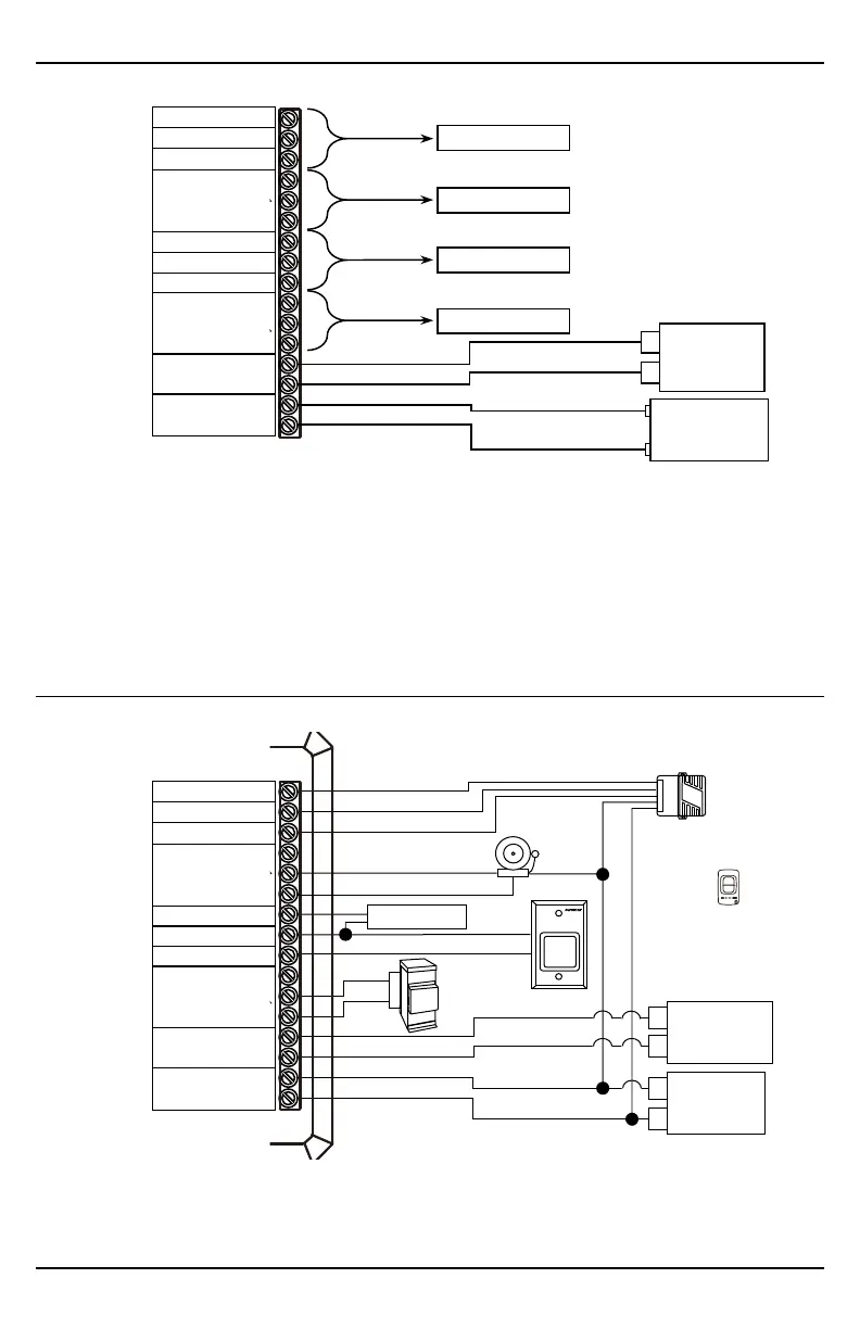
Basic Wiring
NOTES
• When connecting to a backup battery, the battery voltage must be 12VDC ONLY.
• Only a battery can be connected to the backup battery input. Do not connect a power adapter.
• When its optional N.O. switch is activated, the first person-in function suspends the operation of
the timer. If the corresponding relay is turned on before first-person-in is activated, the relay will
remain on until the first-person-in switch is deactivated. Once deactivated, the timer will turn on
the last programmed function prior to the first-person-in activation.
Sample Application
1
An RF receiver can be used to trigger the egress wirelessly. The receiver’s COM terminal is connected to a ground and the N.O. terminal is
connected to the timer's egress input. A second output on the RF can be connected to the first-person-in terminal.
2
A compatible RF transmitter can then be used to trigger the egress, via the RF receiver and the first-person-in function.
3
A gate operator connected to the lock relay output is triggered and opens a gate.
in +
2 3 4 5 6 7 8 9 10
11 12 13 14 15 16
battery +
N.C.
Relay 1 COM
N.O.
Relay 2 COM
N.O.
TO
EXIT
3
Power supply
12~24 VAC or
10~48 VDC
RF receiver
1
2- Button
RF transmitter
2
Shunt switch
Lead acid
backup battery
12VDC
in +
2 3 4 5 6 7 8 9 10
11 12 13 14 15 16
battery +
N.C.
Relay 1 COM
N.O.
Relay 2 COM
N.O.
Power supply
12~24 VAC or
10~48 VDC
Lead acid
backup battery
12VDC
N.O. Ground switch
Device 2
Device 1
N.O. Ground switch
 Loading...