A C-TRAC2.1 MANUAL
IOM-12 Page 14 March 1999 R1
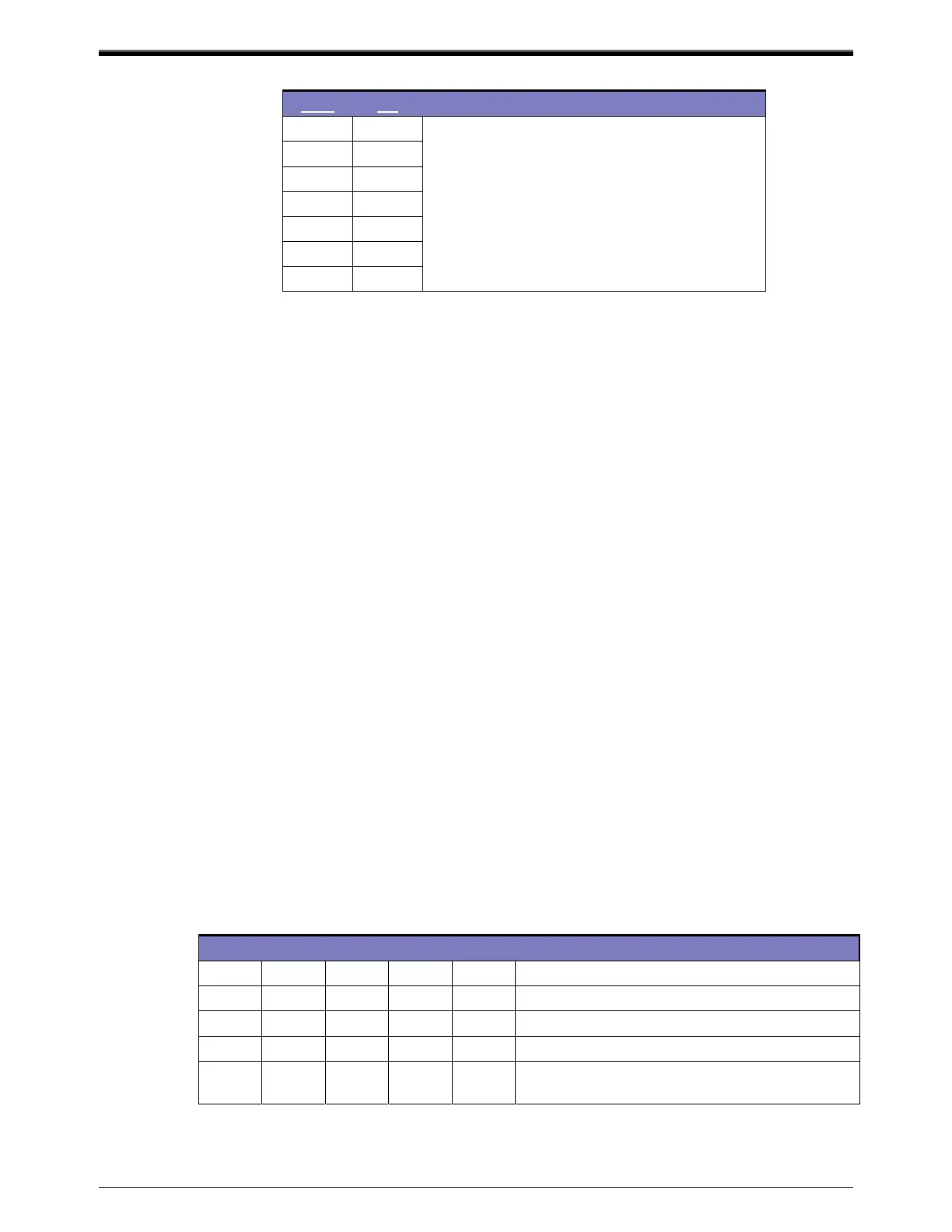
VDC Ma
0
0
2
3
Note: Zero reset considered to be about 5.5 VDC
or 12 ma less is resetting down to cooler
discharge greater is resetting up to warmer
discharge
4
8
5
10
6
12
8
16
10
20
Calibration Method 1
Remove the discharge sensor and install a 1000-ohm 1% ¼ watt resistor in place of the sensor.
Adjust the discharge set point until the internal time delay activated light goes off, and is mid way
between the two on points. Set the incoming signal to either 12 ma or 5.5 VDC. Turn on dipswitch 5.
Gradually adjust pot 10 (mounted on the underside of the board) until the internal time delay activated
light goes off, and is mid way between the two on points.
Calibration Method 2
Install the temperature simulator pot and adjust the simulator temperature pot until the internal time
delay activated light goes off, and is mid way between the two on points. Set the incoming signal to
either 12 ma or 5.5 VDC. Turn on dipswitch 5. Gradually adjust pot 10 (mounted on the underside of the
board) until the internal time delay activated light goes off, and is mid way between the two on points.
XVIII. CALCULATED SET-POINT
The calculated set point is an internal calculation of the C-TRAC electronics. If no reset devices are
activated (dipswitches 2, 3, 4, 5 are off). The calculated set point and set point knob are the same value. If,
however, one of the reset functions is activated, the calculated set point also includes the affect of that
reset devices desire to adjust the set point up or down.
XIX. DISCHARGE TEMPERATURE SENSING
A duct sensor senses discharge temperature. There are often two discharge sensors on the C-TRAC, one
for heat control and one for cool control. A relay will switch between them. This is to avoid hunting
problems introduced by the thermal mass of the cooling coil.
XX. SET-POINT CALIBRATION
Set point calibration should not need to be done as it was set at the factory. The Johnson Control TE 6000-
960 and the TE 6100-960 combination set point and sensor is pre-calibrated at Johnson's factory. The
Engineered Air C-TRAC2.1 has been calibrated at the Engineered Air factory.
1. To determine what control options this C-TRAC is configured to operate with check the wiring diagram,
control function, or C-TRAC dipswitch settings. The types of control are listed below.
2. Locate the dipswitches under the removable cover. Write down their present settings. After calibration
return the switches to their original settings.
SW1 SW2 SW3 SW4 SW5 REMARKS
On
Off Off Off Off Discharge control
Off
On Off Off Off Room control (not recommended)
On
Off On Off Off Discharge control c/w room or return reset
On
Off Off On Off Discharge control c/w ambient reset
On
Off Off Off On
Discharge control c/w 4-20 ma, 0-10 VDC or
vane position reset
Calibrate the required individual sensor and set points combination in the following order. Do not attempt to
calibrate any application listed below that is not part of your application.