A C-TRAC2.1 MANUAL
IOM-12 Page 4 March 1999 R1
VIII. POTS AND DIP SWITCH CHART
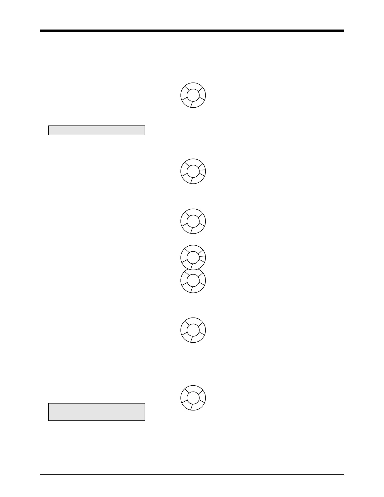
P1 NIGHT SETBACK
To adjust the amount of heat for
night below the room dial set point,
first terminal “k” must be powered
with 24 VAC on it. This locks off
mech. cooling, econo and lowers
the room heat by the temp set on
pot.
NOTE: You need room sensor.
P2 DISCHARGE
CALIBRATION
To calibrate the set point dial on the
front of the C-TRAC2.1. To use this,
“S” and “SP” must be jumped. If an
external set point is wired to U, S,
and M this is still the calibration pot.
There will be no “S-SP” jumper with
external set point.
P3 COOLING DEADBAND
To adjust range in which discharge
temp. will not switch cool stages.
P4 CALIBRATION FOR ROOM
RESET
If the optional control is wired to
terminals V, Y, X, Z.
P5 ROOM RESET FACTOR
Adjusts amount of control the room
thermostat has.
1 = maximum reset
5 = minimum reset
P6 HEAT OFFSET FACTOR
N/A on C-TRAC2.1.
On older C-TRAC’s this pot sets
deadband between heat and cool
set point (heat output terminal HT and
B). This ramped output is also
affected by cooling deadband and
type of heat control in use.
5 = min. offset
1 = max. offset
P7 DAMPER MIN. POS. POT
Note: Some units may use
external pot.
SWITCHES
1 to 5 selects option set point and
sensors.
To test Discharge Air Control only
switch 1=on, switches 2 through
5=off.
To test Room Control only
Switch 1 = off
Switch 2 = on
Switches 3 through 5 = off
Switches 6 and 7 are for
economizer set up.
SWITCH 8 IS TO SHORTEN
MECH. COOLING TIMERS
ENSURE ITS LEFT IN THE OFF
POSITION WHEN YOU FINISH
SERVICING.
LED LIGHTS
C-TRAC2.1 always starts in heat
mode.
HEATING – light on, in heat
mode.
NO HEAT OF COOL LIGHT –
Economizer operation.
COOLING – light on, in cool
mode.
INT. TIME DELAY LIGHT ON –
The discharge temp is not
satisfied and the microprocessor
is going to switch mode or adjust
an output.
COMP. AMBIENT CLOSED
Outside ambient will allow mech.
cooling to operate.
TO SIMULATE A FULL CALL
FOR COOLING
Open circuit discharge sensor.
TO SIMULATE A FULL CALL
FOR HEAT
Short circuit discharge sensor.
12
10
14
6
8
2
3
1
5
4
2
3
1
5
4
50
25
75
100
0
Colder
Hotter
6
9
5
13
11
7
8
Colder
Hotter