A C-TRAC2.1 MANUAL
Page 19 March 1999 R1
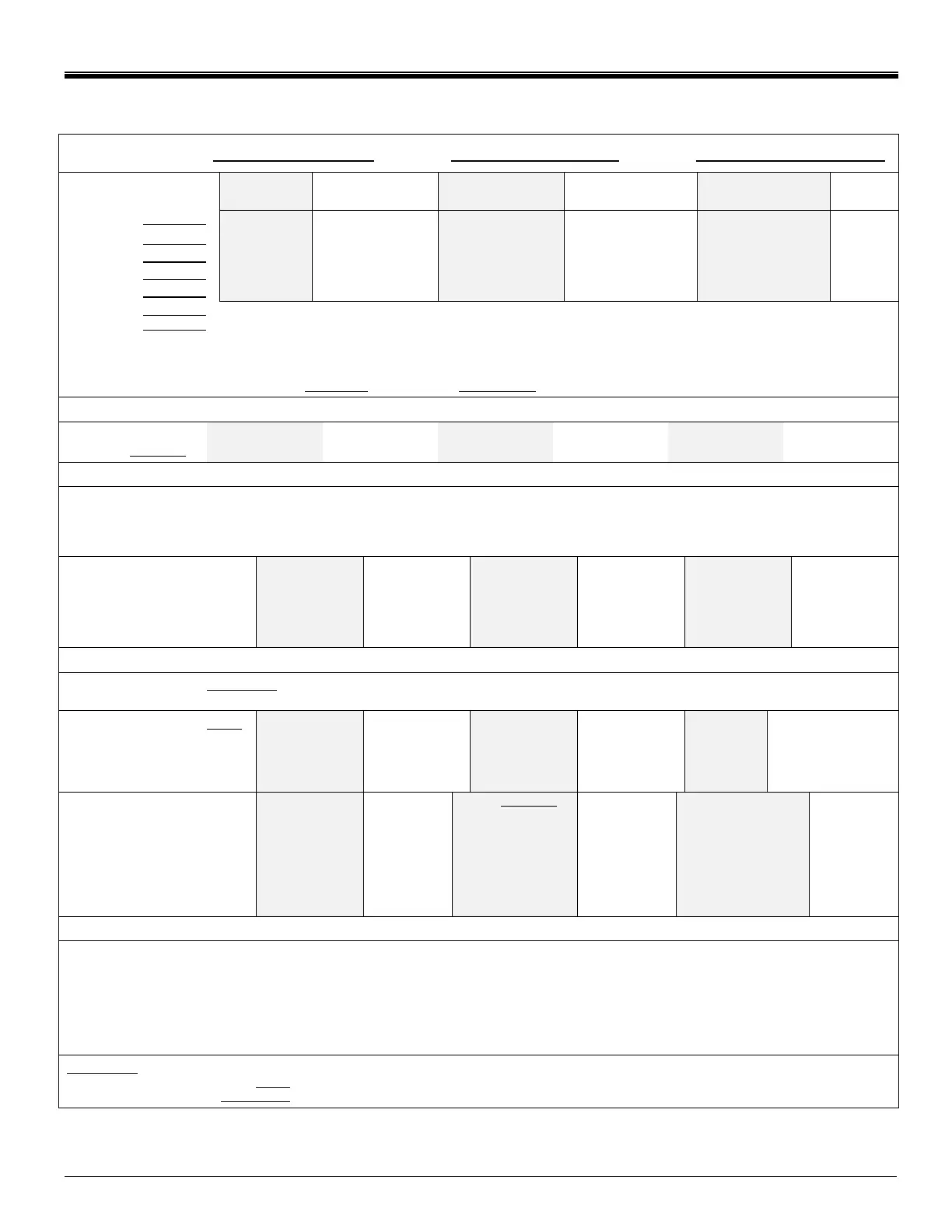
XXI. C-TRAC2.1 SET UP SHEET
C-TRAC2.1 JOB # TAG # DATE
DISCHARGE
ONLY
DISCHARGE C/W
ROOM RESET
DISCHARGE C/W
4-20 / 0-10 RESET
DISCHARGE C/W
AMBIENT RESET
DISCHARGE C/W
VAV POS RESET
ROOM
ONLY
Dip Switch 1
ON ON ON ON ON OFF
Dip Switch 2
OFF OFF OFF OFF OFF ON
Dip Switch 3
OFF ON OFF OFF OFF OFF
Dip Switch 4
OFF OFF OFF ON OFF OFF
Dip Switch 5
OFF OFF ON OFF ON OFF
Dip Switch 6
ON – WHEN TERMINAL E IS POWERED, THE DAMPERS GO TO MINIMUM POSITION
ON – WHEN COMPRESSOR NUMBER ONE IS ON, THE DAMPERS GO TO MINIMUM POSITION
If switches 6 and 7 are both off, the damper locks out and min. pos. must be external to C-TRAC. The C-TRAC will
continuously modulate the damper during mechanical cooling. If there is on economizer, set switches 6 and 7 to the ON
position.
Dip Switch 8 ALWAYS OFF (Service Switch) FOR ALL APPLICATIONS ALWAYS OFF
Dip Switch 7
POT NUMBER (The actual Pot labeling is shown in brackets.)
1. NIGHT SETBACK
(NSB)
Not Used 5,7,10,12,14ºF Not Used Not Used Not Used 5,7,10,12,14ºF
(Use only if terminal K is powered during night operation and C-TRAC is fitted with a room sensor.)
2. DISCHARGE CALIBRATION (DIS CAL) __________ will be set by PRODUCTION, as required.
3. COOLING DEADBAND (COOL DB) __________ 0 or 1 COOLING STAGE = 8ºF 2 COOLING STAGES = 7ºF
3 COOLING STAGES = 6ºF 4 or 5 COOLING STAGES = 5ºF
4. ROOM CALIBRATION (ROOM CAL) __________ will be set by PRODUCTION, as required.
5. ROOM RESET RATIO ____
FACTOR (enter pot pos. #)
(ROOM RESET FACTOR)
Normal – Heat/Cool = 1
– Cool Only = 3
Not Used Reset Range
1 = +32/-10ºF
2 = +18/-6
3 = +12/-4
4 = +9/-3
5 = +7/-2
Not Used Not Used Not Used Not Used
6. POT NOT USED
7. DAMPER MIN. POS. . Adjustable from 0-100% in all cases except when dip switches 6 and 7 are off.
(enter value)
8. ROOM DEADBAND
(enter pot pos#)
OR
AMBIENT RESET RATIO
(Ambient Reset Factor)
Not Used SET TO
POSITION 5
Not Used 1.0 = -15/+7ºF
1.5 = -9/+4
2.0 = -5/+3
3.0 = -2/+1
(normal = 1.5)
Not Used 1 = 0.75ºF
2 = 3 (normal
3 = 6 pos. = 2.5)
4 = 8
5 = 10
9. 4-20 ma / 0-10 V or VAV
VANE POSITION RESET _____
pos#. Normal = 4.5 for V/ma, 3.5
for vanes. Vane reset also
needs the following position info.
MAX. TEMP AT _____% OPEN
MIN. TEMP AT ______% OPEN
(VAV BMS RESET FACTOR)
Not Used POSSIBLE
WITH
SPECIAL
SET UP
SPECS
ºF ºF
POS# F/V F/ma
5 = 25 20
4.5 = 15 12
4 = 9 6
3 = 5 4
2 = 4 2.5
POSSIBLE
WITH
SPECIAL SET
UP SPECS
POS# RESET(ºF)
5 = 20
4.5 = 12
4 = 6
3 = 4
2 = 2.5
Not Used
10. 0-10 V / 4-20 ma CALIBRATION BMS VAV CAL.: PRODUCTION TO POSITION AS REQUIRED DURING INITIAL SET UP
11. HEATING CONTROL BAND SETTING _______
(HEAT ENVEL) (enter pot pos#)
For NO HEAT applications set to 5.
(NOTE: If sensor is downstream of the cooling coil subtract
0.5 from the required setting.)
1. Select the column corresponding to the selected cooling deadband.
2. Select the row corresponding to the required heating controller.
3. Find the intersect COOLING DEADBAND (F as per pot #3).
4 5 6 7 8 10 pot #11
HEATING 109/DJM 2.5 3.0 3.5 3.5 4.0 4.0 required
CONTROL G-TRAC/H-TRAC 3.0 3.5 4.0 4.5 5.0 5.0 position
SELECTION HEATING COIL 2.0 2.0 2.5 2.5 3.0 3.5
SETPOINTS
DISCHARGE SETPOINT VALUE
ROOM SETPOINT VALUE
DISCHARGE SETPOINT LOCATION (circle)
ROOM SETPOINT LOCATION (circle)
INTERNAL
PANEL MOUNTED
PANEL MOUNTED
REMOTE
REMOTE
IN ROOM