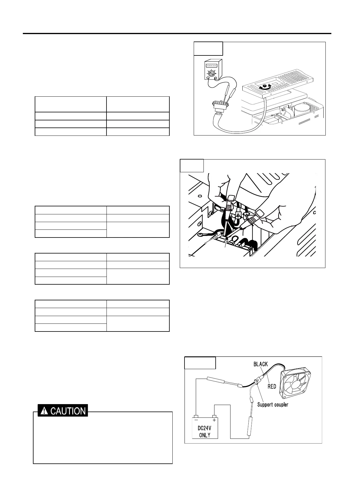
【Check 5】 Resistance of Control Assy (Fig.5)
◇Checking point
Remove 6pin coupler.
Test result
Dial position OFF ~ 5
Approx. 17kΩ~5kΩ Normal
∞Ω Broken
0Ω Short Circuit
【Check 6】 Check the temperature controller.
(Fig.6)
◇Checking points
<Use power AC100-240V>
(Ambient temp 25℃)
Test result Judge
Approx. DC12-14V Normal
DC 0 V
12V less than
<Use power DC12V>
(Ambient temp 25℃)
Test result Judge
Approx. DC12V Normal
DC 0 V
11V less than
<Use power DC24V>
(Ambient temp 25℃)
Test result Judge
Approx. DC24V Normal
DC 0 V
23V less than
【Check 7】 Checking the operation of the fan motor.
(Fig.7)
◇Checking point
If want to check the start-up of the fan motor directly,
can check by connecting the DC24V directly. (Fig.7)
5. CHECKING POINT & METHOD
Check the resistance at between terminals
brown and black.
Check the voltage at between terminals ORANGE
and BLACK.
Temperature controller is
broken
Temperature controller is
broken
Temperature controller is
broken
・Please be careful not to mistake the polarity
of the power supply.
・When connect with DC24V or wrong polarity,
fan motor will fail.
・Please use such as support coupler so as
not to short-circuit power.