Installation and Operation Manual
●
Fan Coil Controller – EZstat
EC-EZstat
Date: 9-2014 Supersedes: NEW
Engineered Comfort reserves the right to change any information concerning product or specification without notice or obligation.
Page 34 of 36
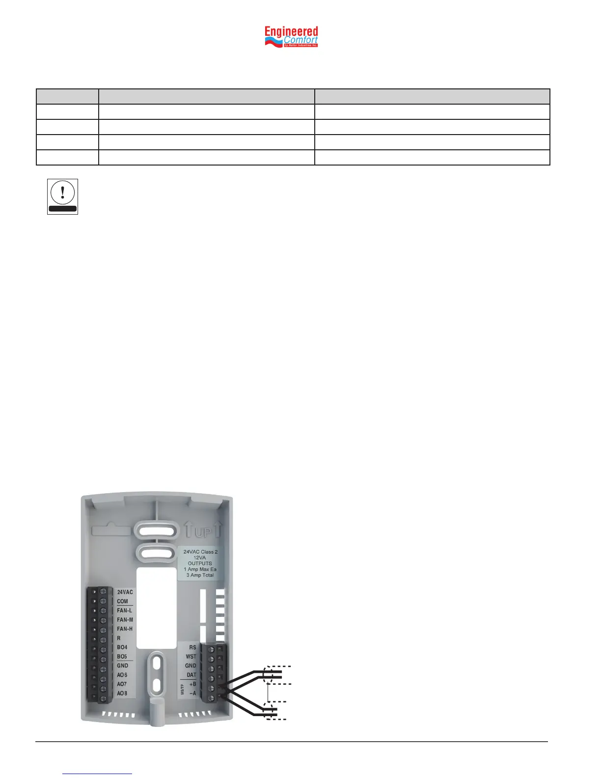
Illustraon8–1BACnetMS/TPnetworkwiring
The dierence between the PID Loop types.
• CLLOOP/HTLOOP-directlycontrolsthefanandmodulatesoofroomtemperature
• CL_DAT LOOP/HT_DAT LOOP - modulate to the DAT setpoints. The valves are controlled o these loops.
8.2 ConnecngtoMS/TPnetwork
Before connecng the EZstat to a BACnet MS/TP network, congure the network properes. See the topic Set up
communicaons in for the procedure to set the following:
• Device instance
• MAC address
• Baud
Use the following principles when wiring the EZstat to an MS/TP network:
• Connect no more than 128 addressable BACnet devices to one MS/TP network. The devices can be any mix of EZstat
controllers, other BACnet controllers, or BACnet routers.
• To prevent network trac bolenecks, limit the MS/TP network size to 60 controllers.
• Use 18 gauge, twisted pair, and shielded cable with capacitance of no more than 51 picofarads per foot for all network
wiring. Belden cable model #82760 meets the cable requirements.
• Connect the ‑A terminal in parallel with all other ‑ terminals. Connect the +B terminal in parallel with all other +
terminals. Connect the shield to an earth ground at one end only.
• Use a KMD‑5575 repeater between every 32 MS/TP devices or if the cable length will exceed 4000 feet (1220 meters).
Use no more than seven repeaters per MS/TP network.
• Place a KMD‑5567 surge suppressor in the cable where it exits a building.
+B
NOTE
Value object Name Descripon
LOOP1 CL LOOP Cooling Loop
LOOP2 HT LOOP Heang Loop
LOOP3 CL_DAT LOOP Cooling Loop
LOOP4 HT_DAT LOOP Heang Loop
Table8-9 PIDcontrolloops
 Loading...