Installation and Operation Manual
●
Fan Coil Controller – EZstat
EC-EZstat
Date: 9-2014 Supersedes: NEW
Engineered Comfort reserves the right to change any information concerning product or specification without notice or obligation.
Page 8 of 36
Turn Counterclockwise unl
the screw engages the base.
4.2 ConnecngInputs
The inputs for the EZstat are congured for specic funcons and do not require set up in the eld. Not all inputs are
required for every model or applicaon.
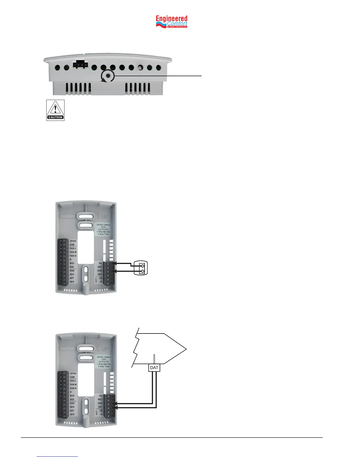
Remotespacetemperaturesensor(oponal)
Connect a 10kΩ, Type II thermistor temperature sensor (Nailor part #H1‑1989) to the remote space temperature (RS)
input and ground (GND) terminals. The input includes the internal pull‑up resistor. Follow the instrucons supplied with
the sensor for installaon.
When a remote space temperature input is connected to the EZstat, the remote temperature is used instead of the
internal temperature sensor.
Fig. 4-1 Wiring for remote space temperature sensor
To prevent mounng screw heads from toughing the circuit board in the controller, use only the mounng
screws supplied. Using screws other than the type supplied may damage the EZstat unit.
RS
GRD
7. Turn the Allen screw counterclockwise unl it backs out of the mounng base and engages the case.
Discharge air temperature
Connect a 10kΩ, Type III thermistor temperature (Nailor part #H1‑0246) probe to the discharge air temperature (DAT)
input. The input includes the internal pull‑up resistor.
Fig. 4-2 Wiring for Discharge Air Temperature Sensor
GND
DAT