Installation and Operation Manual
●
Fan Coil Controller – EZstat
EC-EZstat
Date: 9-2014 Supersedes: NEW
Engineered Comfort reserves the right to change any information concerning product or specification without notice or obligation.
Page 9 of 36
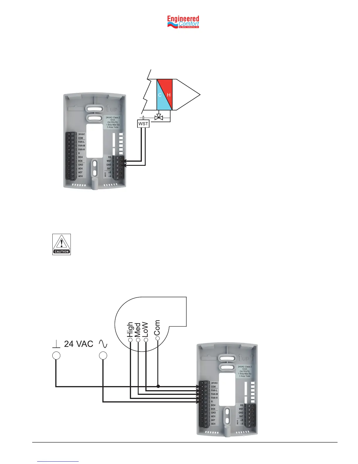
Water temperature sensor
Connect a 10kΩ, Type III thermistor temperature probe (Nailor part #H1‑1764B) to the water temperature (WST) input.
The input includes the internal pull‑up resistor. Follow the instrucons supplied with the sensor for installaon.
4.3 ConnecngOutputs
The EZstat outputs are congured for specic applicaons.
• Depending on the conguraon, the EZstat outputs are designed for either 24 VAC or 0‑10 VDC loads.
• The outputs may represent analog or digital signals.
Fig. 4-3 Wiring for a water temperature sensor
Improperly connecng loads or equipment to output terminals may damage the equipment.
Connect only as shown in the following diagrams or applicaon drawings.
WST
GND
Connecngtoathree-speedfan
The following diagram shows the connecons for a three‑speed fan. The fan circuits must be a 24 VAC pilot duty only.
• For a single‑speed fan, use only the FAN‑L connecon.
• For a three‑speed, use FAN‑L, FAN‑M, and FAN‑H
Fig. 4-4
Conneconstoa
three-speed fan
COM
FAN-L
FAN-H
FAN-M
R
 Loading...