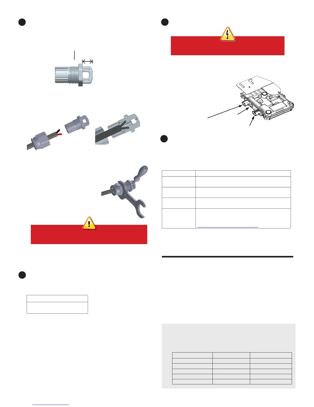
Terminate the Unused End of the Cable
A ) Remove 13 mm (1/2”) of the cable sheath from
the conductors. Use the terminator loop to measure.
B ) Slide the hex nut onto the cable. There is a grommet inside of the
terminator body that should remain in place.
C ) Insert the cable into the terminator body so that each of the two
wires land on opposite sides of the internal separator.
D ) Insert a screwdriver into the slot on the top of the terminator to
hold it in place, and torque the nut to 7 Nm.
E ) Hold the terminator body stationary with
the screwdriver and turn only the hex nut
to prevent the conductors from twisting
out of the separator.
F ) Attach the terminated cable end to the
PV racking with a cable clip or tie wrap
so that the cable and terminator do not
touch the roof.
Connect the PV Modules
A ) Connect the DC leads of each PV module to the DC input connectors
of the corresponding microinverter.
B ) Check the LED on the connector side of the microinverter. The LED
ashes six times when DC power
is applied.
C) Mount the PV modules above the
microinverters.
ACTIVATE MONITORING AND CONTROLS
DANGER! Electric shock hazard. The DC conductors of
this PV system are ungrounded and may be energized.
7
WARNING: The terminator can not be re-used. If you
unscrew the nut, you must discard the terminator.
After you have installed the microinverters, follow the procedures in the
Enphase IQ Envoy Quick Install Guide to activate system monitoring, set
up grid management functions, and complete the installation.
•
Connecting the IQ Envoy
•
Detecting devices
•
Connecting to Enlighten
•
Registering the system
•
Building the virtual array
Energize the System
A ) Turn ON the AC disconnect or circuit breaker for the branch circuit.
B ) Turn ON the main utility-grid AC circuit breaker. Your system will start
producing power after a ve-minute wait time.
C ) Check the LED on the connector side of the microinverter:
LED Indicates
Flashing green Normal operation. AC grid function is normal and
there is communication with the IQ Envoy.
Flashing orange The AC grid is normal but there is no
communication with the IQ Envoy.
Flashing red The AC grid is either not present or not within
specication.
Solid red There is an active “DC Resistance Low, Power Off”
condition. To reset, refer to the Enphase IQ Envoy
Installation and Operation Manual at:
http://www.enphase.com/support.
9
10
Status
LED
Terminator Body
13mm
AC connector
DC connector
Complete Installation of the Junction Box
A) Connect the Enphase Q Cable into the junction box.
The Q Cable uses the following wiring color code:
Wire Colors
Black – L1
Red – L2
8
Internal View
Enphase Connector Rating
Enphase Connectors on the cable assemblies in the following table have a
maximum current of 20 A, a maximum OCPD of 20 A, and maximum ambient
temperature of -40° to +79° C (-40° to +174.2° F) and are rated for disconnection
under load.
Part Number Model Maximum Voltage
840-00387 Q-12-10-240 250 VAC
840-00388 Q-12-17-240 250 VAC
840-00389 Q-12-20-200 250 VAC
840-00385 Q-DCC-2 100 VDC
840-00386 Q-DCC-5 100 VDC

 Loading...


