INSTALLATION
Plan a location for the IQ Batteries
The IQ Battery housing is NEMA type 3R and can be installed indoors or out-
doors. The terminal blocks accepts copper conductors of No. 14 - 8 AWG.
A ) Following local standards, choose a well-ventilated location where
the ambient temperature and humidity are within -15° C to 55° C
(5° F to 131° F) and 5% to 100% RH, non-condensing, preferably
out of direct sunlight. The optimum ambient temperature range
for installation location is 0º C to 30º C (32º F to 86º F). Provide
smoke alarms in the residence in accordance with building, re and
installation codes.
B ) Ensure that the mounting location can sustain the total weight
of the IQ Batteries and mounting bracket. Total weight for the IQ
Battery 3T, including the IQ Battery base unit, cover and wall mount
bracket, is 48.8 kg (107.6 lbs). Total weight for the IQ Battery 10T,
including the three IQ Battery base units, cover, and wall mount
bracket, is 143.6 kg (316.5 lbs).
* WARNING: The installer should install blocking between studs
to ensure that no single stud carries the entire weight load of the
IQ Batteries.
C ) Plan the mounting location to be at least 15cm (six inches) off the
ground and 15cm (six inches) from the ceiling for IQ Battery 3T.
Plan the mounting location to be at least 15cm (six inches) off the
ground and 91cm (thirty-six inches) from the ceiling for IQ Battery
10T.
Keep the IQ Battery away from falling or moving objects, including
motor vehicles.
* WARNING: If mounted in the path of a motor vehicle, we
recommend a mounting height that is 91 cm (thirty-six inches)
minimum above the oor.
D ) Ensure that there are no pipes or electrical wires where you plan to drill.
E ) Plan to maintain at least 91cm (thirty-six inches) of clearance in
front of each IQ Battery.
F ) Consider the dimensions of the IQ Batteries, easy access, height,
and length of cable when selecting the location.
G ) Select a location where you can interconnect to the Enphase IQ
System Controller.
H ) Follow all local standards and restrictions set forth by AHJ
(Authority Having Jurisdiction).
I ) Up to two IQ Battery 10T (or six IQ Battery 3T) units can be daisy
chained on a single branch circuit. For installations with more than
this number of units, there must be a separate load center, subpanel,
or circuit combiner with over current protection to combine the
daisy chained circuits, and you must run only one circuit for all
the IQ Battery units to the IQ System Controller (or to Enphase IQ
Combiner for grid-tied-only installations). You must select proper
conductors and circuit breakers for these circuits according to local
codes, standards, and other applicable requirements. IQ System
Controller supports up to a maximum of 80 A breaker for IQ Battery
connection circuit.
The subpanel could be a small, two circuit box with circuit breakers.
The circuit breakers in the box would have to be suitable for
back-feeding, per NEC 408.36(D).
Select the right size subpanel and breakers based on the number of
IQ Battery units being installed. Up to four IQ Battery 10Ts or twelve IQ
Battery 3Ts can be safely connected to 80A load center.
To do this, you must purchase an off-the-shelf subpanel and install
as shown in the image in next column.
J ) The maximum conductor size for IQ Battery 3T and IQ Battery 10T is
8 AWG and the maximum breaker rating with this conductor size is
40 A.
1
Install the AC disconnect
Following all local codes and standards:
A ) Install an AC disconnect that can break the maximum rated current
of the branch circuit under load. The AC disconnect must be readily
accessible and located within line-of-sight of IQ Battery, per NEC
2017 706.7(A).
B ) Each IQ Battery unit is suitable for use with up to No. 8 AWG wires
on a maximum 40 A branch circuit. If more than 32 A of IQ Batteries
(corresponding to a 40 A branch circuit) are installed, a separate sub-
panel must be installed between the IQ Battery units and IQ System
Controller to combine the IQ System Controller circuits together. All
circuit breakers in the subpanel must be suitable for back-feeding, per
NEC 408.36(D).
C ) Verify that AC voltage at the site is within range: single-phase L1 to L2
voltage must measure between 211 and 264 VAC, while L-N should
measure between 106 and 132 VAC.
2
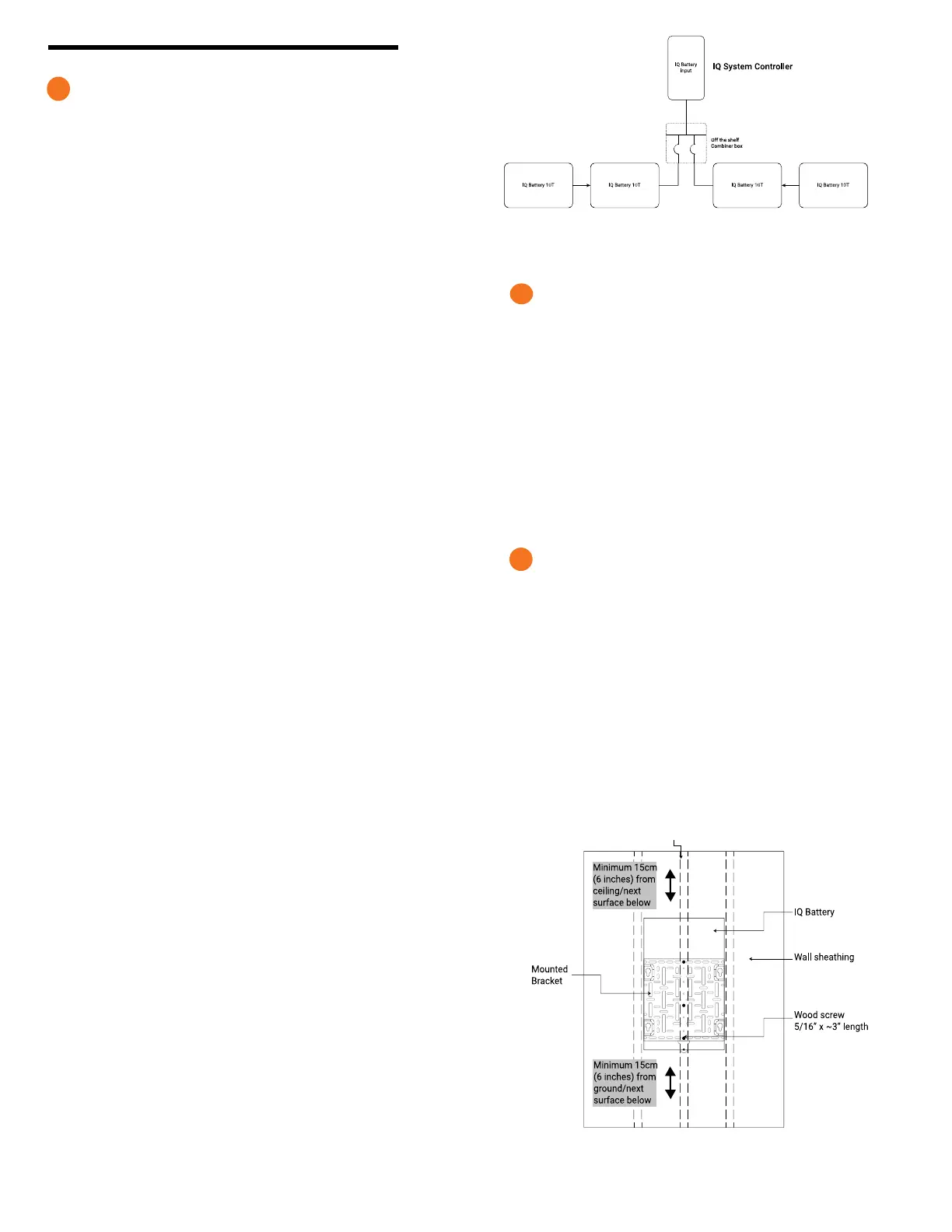
Prepare to install the wall-mount bracket
A ) Make sure that the planned position for the wall-mount bracket
meets clearance requirements as shown. The image depicts a
single-width bracket for the IQ Battery 3T, but clearances and
requirements are the same when installing a triple-width bracket for
the IQ Battery 10T.
B ) Ensure that the mounting location can sustain the weight of
the IQ Batteries and mounting bracket. Total weight for the IQ
Battery 3T including the mounting brackets and cover is 48.8 kg
(107.6 lbs), while the total weight for IQ Battery 10T including the
mounting bracket and cover add up to 143.6 kg (316.5 lbs).
C ) Starting at installation position closest to the power source, mark a
level line on the wall as a guide.
* WARNING! Multiple risks. Make sure not to drill or attach into
electric wiring or pipes that are in the wall!
3
Mounting on vertical stud
IQ Battery 3T
NOTE: The above shown image is just for reference. Use other slots
on the wall mount if additional xing is required for stability (To be
assessed by the installer).
* WARNING: Parallel power production sources only. Do not connect
load circuits.

 Loading...


