INSTALLATION
Plan a location for the IQ Batteries
The IQ Battery housing is NEMA type 3R and can be installed indoors or out-
doors. The terminal blocks accept copper conductors of No. 14–8 AWG.
A ) Following local standards, choose a well-ventilated location where
the ambient temperature and humidity are within -15°C to 55°C
(5°F to 131°F) and 5% to 100% RH, non-condensing, preferably out
of direct sunlight. The optimum ambient temperature range for
installation location is 0ºC to 30ºC (32ºF to 86ºF).
B ) Ensure that the mounting location can sustain the total weight of
the IQ Batteries and mounting bracket. The Total weight for the IQ
Battery 3, including the IQ Battery base unit, cover and wall-mount
bracket, is 52 kg (114.6 lb). Total weight for the IQ Battery 10,
including the three IQ Battery base units, cover, and wall-mount
bracket, is 154.7 kg (341 lb).
* WARNING: The installer should install blocking between studs
to ensure that no single stud carries the entire weight load of the
IQ Batteries.
C ) Plan the mounting location to be at least 15 cm (6 inches) off the
ground and 15cm (6 inches) from the ceiling. Keep the IQ Battery
away from falling or moving objects, including motor vehicles.
* WARNING: If mounted in the path of a motor vehicle, we
recommend a mounting height that is 91 cm (36 inches) minimum
above the oor.
D ) Ensure that there are no pipes or electrical wires where you plan to drill.
E ) Plan to maintain at least three feet of clearance in front of each
IQ Battery. Allow at least 15cm (6 inches) clearance on the top and
bottom of the IQ Battery so that the vents on the top and bottom of
the units are not blocked for air circulation.
F ) Consider the dimensions of the IQ Batteries, easy access, height,
and length of cable when selecting the location.
G ) Select a location where you can interconnect to the
Enphase IQ System Controller.
H ) Follow all local standards.
J ) Review your external conduit plan to determine to which side of the
eld wiring compartment you will connect the conduit.
K ) Up to two IQ Battery 10 (or six IQ Battery 3) units can be dai-
sy-chained on a single branch circuit. For installations with more
than this number of units, there must be a separate load center,
subpanel, or circuit combiner with overcurrent protection to com-
bine the daisy-chained circuits, and you must run only one circuit for
all the IQ Battery units to the IQ System Controller (or to
Enphase IQ Combiner for grid-tied-only installations). You must
select proper conductors and circuit breakers for these circuits
according to local codes, standards, and other applicable require-
ments. IQ System Controller supports up to a maximum of 80 A
breakers for IQ Battery connection circuit.
The subpanel could be a small, two-circuit box with circuit breakers.
The circuit breakers in the box would have to be suitable for
back-feeding, per NEC 408.36(D).
Select the subpanel and breakers of the right size based on the
number of IQ Battery units being installed. Up to four IQ Battery 10s or
twelve IQ Battery 3s can be safely connected to 80 A load center.
To do this, you must purchase an off-the-shelf subpanel and install it
as shown in the following image:
* WARNING! Parallel power production sources only. Do not
connect load circuits.
1
Install the AC disconnect
Following all local codes and standards:
A ) Install an AC disconnect that can break the maximum rated current
of the branch circuit under load. The AC disconnect must be readily
accessible and located within line-of-sight of IQ Battery, per NEC 2017
706.7(A).
B ) Each IQ Battery unit is suitable for use with up to No. 8 AWG wires
on a maximum 40 A branch circuit. If more than 32 A of IQ Batteries
(corresponding to a 40 A branch circuit) are installed, a separate
subpanel must be installed between the IQ Battery units and
IQ System Controller to combine the IQ System Controller circuits
together. All circuit breakers in the subpanel must be suitable for
back-feeding, per NEC 408.36(D).
C ) Verify that AC voltage at the site is within range: single-phase L1 to L2
voltage must measure between 211 and 264 VAC, while L-N should
measure between 106 and 132 VAC.
2
Prepare to install the wall-mount bracket
A ) Make sure that the planned position for the wall-mount bracket meets
clearance requirements as shown. The image depicts a single bracket,
but clearances and requirements are the same for the triple-width
bracket.
B) Ensure that the mounting location can sustain the weight of the
IQ Batteries and mounting bracket. Total weight for the IQ Battery
3, including the mounting brackets and the cover is 52 kg (114.6 lb),
while the total weight for IQ Battery 10, including the mounting bracket
and cover adds up to 154.7 kg (341 lb).
C ) Starting at the installation position closest to the power source, mark
a level line on the wall as a guide.
* WARNING! Multiple risks. Make sure not to drill or attach to
electric wiring or pipes that are in the wall!
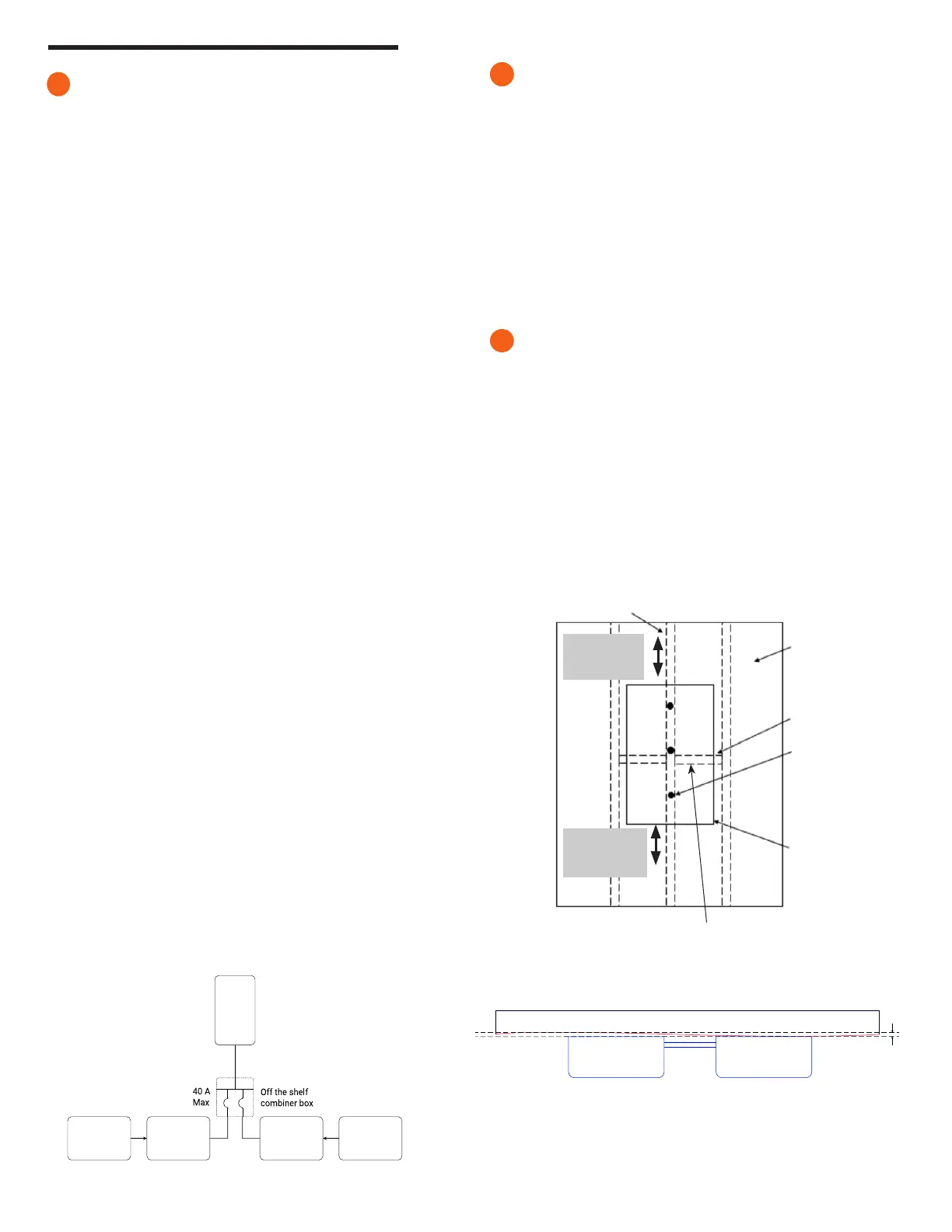
3
Minimum 15cm
(6 inches) from
ground/next
surface below
Minimum 15cm
(6 inches) from
ceiling/next
surface above
Blocking installed
between studs
Wood screw
7.6 cm (#10x3”)
IQ Battery
Wall
sheathing
Mounted
bracket
Wood stud
Mounting Surface
Flatness (Across
the Installation
width and height)
recommended to
be within 2 mm*
✓ NOTE: The above-specied surface atness requirement is applicable to
all the combinations of IQ Battery 3 and 10.
* If the difference in atness is more than 2 mm, recommend installing a substructure like unistrut for
better alignment of the units.
MOUNTING WALL
IQ Battery IQ Battery
IQ Battery
Input
Single circuit between combined
IQ System Controller and IQ Battery
IQ Battery 10
IQ Battery 10
IQ Battery 10 IQ Battery 10
IQ System Controller
 Loading...


