Install conduit and eld wiring, continued
+ DANGER! Risk of electric shock. Check that the dedicated circuit
breaker protecting the branch where the IQ Battery(ies) will be
connected is turned off before wiring.
* WARNING! Risk of equipment damage. The DC switch must be
OFF before installing; otherwise, IQ Battery will try to form a grid.
D ) If installing an IQ Battery 10, install the inter-unit raceways. The
left-side and right-side conduit openings are different diameters, so
you must install the raceway in the proper direction.
•
Face the fronts of the batteries,
and insert the raceway through
the right-hand unit’s left-side
conduit opening from within
the eld wiring compartment,
with the arm of the raceway
pointing up.
•
Push the raceway through the right-hand unit’s left-side conduit
opening and into the left-side unit’s right-side conduit, opening until the
two snap features on the raceway engage the left-side unit’s enclosure.
•
Once fully inserted, rotate the “arm” toward you until it stops.
•
The left-side conduit opening of each battery unit has a at surface
without additional features. The larger seal (green) on the raceway
mates with this opening. The right-side conduit opening has a
groove around the hole to t the O-ring (red) of the raceway. Make
sure that the O-ring is captured in the groove between the IQ Battery
enclosure and the raceway ange adjacent to the O-ring.
6
E ) Using the conductors and suitable conduits, connect the AC dis-
connect and the rst adjacent IQ Battery. Use the conduit openings
provided to connect the conduit and pass the wires through them.
Note that if an Enphase IQ System Controller is in line-of-sight, the
breaker can service as a disconnect.
* WARNING! Risk of equipment damage. Do not modify or rewire
the pre-installed wiring or bonding connections in the eld wiring
compartment.
* WARNING! Risk of equipment damage. Always connect to two
Lines (active) and one ground.
F ) Connect each wire in the eld wiring compartment to its corre-
sponding conductor (Lines and Ground). Each terminal accepts two
14–8 AWG conductors (11 mm or 7/16 inch strip length). Tighten to
a torque of 14 lb-in.
G ) If installing an IQ Battery 10, route the wires from the rst
IQ Battery to the adjacent IQ Battery through the inter-unit raceway.
There are two positions for each line and for ground in the terminal
block to allow for daisy-chaining.
* WARNING! Risk of equipment damage. Do not daisy chain
more than six total IQ Battery 3 or two IQ Battery 10 on a single
branch circuit.
H ) After all wires in the eld wiring compartment are connected and
secured, check that there are no exposed conductors.
I ) If connecting additional IQ Batteries, use another conduit and
another set of wires to connect between eld wiring compartments.
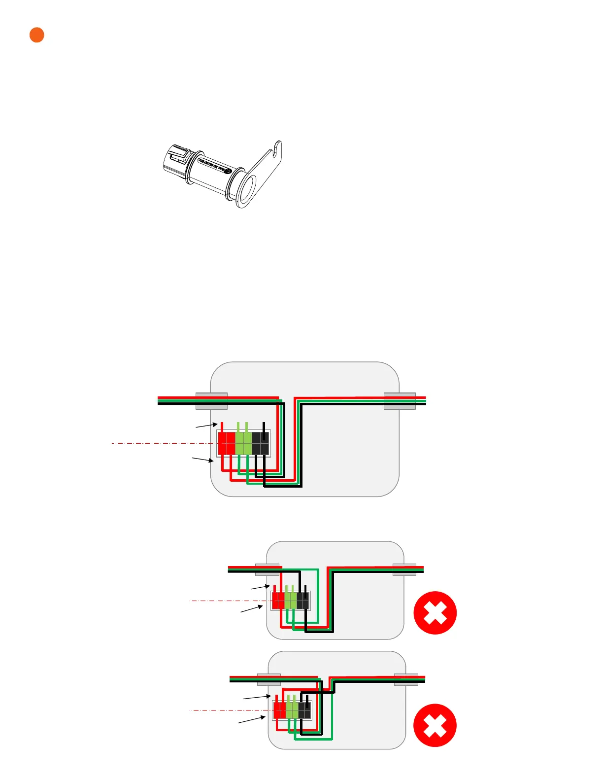
Inter-unit
raceway
Factory connections side
Field wiring side
To adjacent IQ Battery 3/10
or IQ System Controller
To adjacent IQ Battery 3/10
or IQ System Controller
Factory connections side
Field wiring side
To adjacent
IQ Battery 3/10 or
IQ System Controller
To adjacent IQ Battery 3/10
or IQ System Controller
Factory
connections side
Field wiring side
To adjacent
IQ Battery 3/10 or
IQ System Controller
To adjacent IQ Battery 3/10 or
IQ System Controller
Correct wiring
Always connect the eld wiring to the terminal blocks from the eld wiring side, as shown below.
Incorrect wiring
Do not connect any eld wiring to the terminal block from the factory connections side.
 Loading...


