Cover and energize the system
* WARNING: Before energizing, make sure that all IQ Batteries in the
system are properly installed and conductors terminated.
✓ NOTE: Check the box for updates on cover installation instructions.
A ) Check that the eld wiring compartment cover(s) for all IQ Batteries in
the system are closed and secured.
+ DANGER: Risk of electric shock. Before continuing, check that
IQ Battery units are properly wired and ground connection does not
have an L1 or L2 connection, as this introduces a safety hazard.
• Apply AC power to the IQ Battery circuits. Do NOT turn On the DC switch on
IQ Batteries.
• Using a voltmeter measure the IQ Battery chassis metal to ground (e.g.,
grounded conduit) and ensure no AC voltage source is present. If wiring is
incorrect, a ground fault may exist, and the AC voltage may read ~120 VAC.
If voltage is present, DO NOT touch the chassis, and immediately remove
AC power from the IQ Battery circuits.
• Remove AC power to the IQ Battery circuits and correct the wiring.
* WARNING: Before commissioning, the DC switch on the IQ Battery
shall not be turned on unless instructed in the Enphase Installer App.
Turning the DC switch On before it is instructed in the Enphase Installer
App can damage the IQ Battery.
8
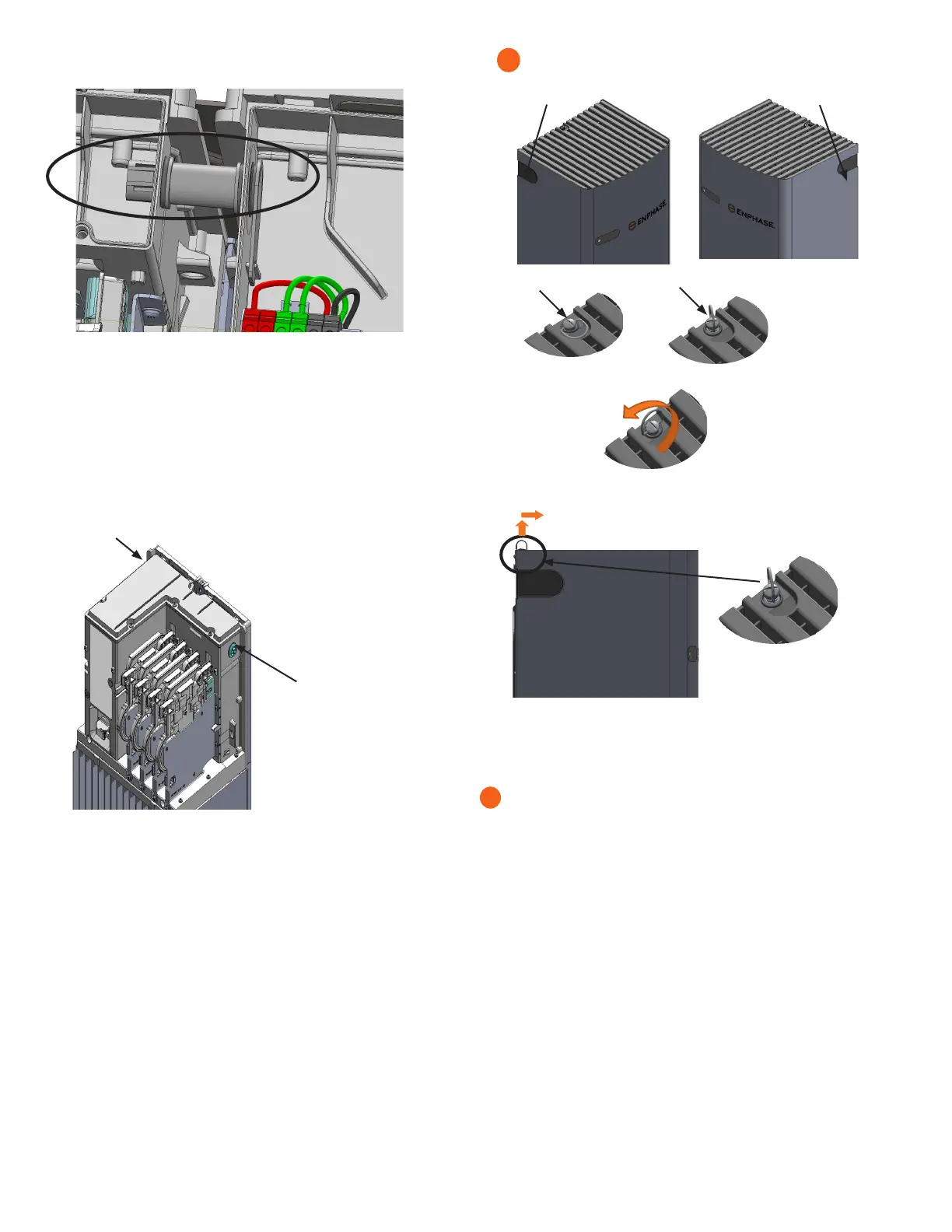
K ) Plug any unused conduit openings before proceeding.
L ) Replace the eld wiring compartment cover. Use a cross-head
screwdriver to tighten the cover screws to 2.3 N m (20.3 Ib-in).
* WARNING! Risk of equipment damage. Ensure that no wires are
pinched before replacing the cover.
+
DANGER! Risk of electric shock. The system is not ready to
be energized! Do not close the circuit breaker or turn on the DC
switch.
The grommet is to be installed on the
left side or right side when the hole in
the left side or right side is not used
for cable routing.
(To be used in IQ Battery 3 when no
conduit is used with the hole).
(To be used in the rightmost base unit
in IQ Battery 10 when no conduit is
used with the hole).
Dismounting of IQ Battery 3 Cover
A) Remove the conduit covers from either side of the IQ Battery cover.
B) Lift up the ring of the quarter-turn screw.
C) Turn the ring in the anticlockwise direction to unlock the screw.
D) After unlocking, hold the ring of the screw and lift the top cover
up slightly and pull it away from the wall in the indicated direction.
E) While pulling out the cover, make sure that the indicated
snaps at the bottom of the unit are being unlocked.
F) Simillarly, to dismount the IQ Battery 10 Cover, please follow the
instructions from A to E.
7
J ) Gently arrange all the wires and connectors inside the eld wiring compart-
ment.
 Loading...


