4
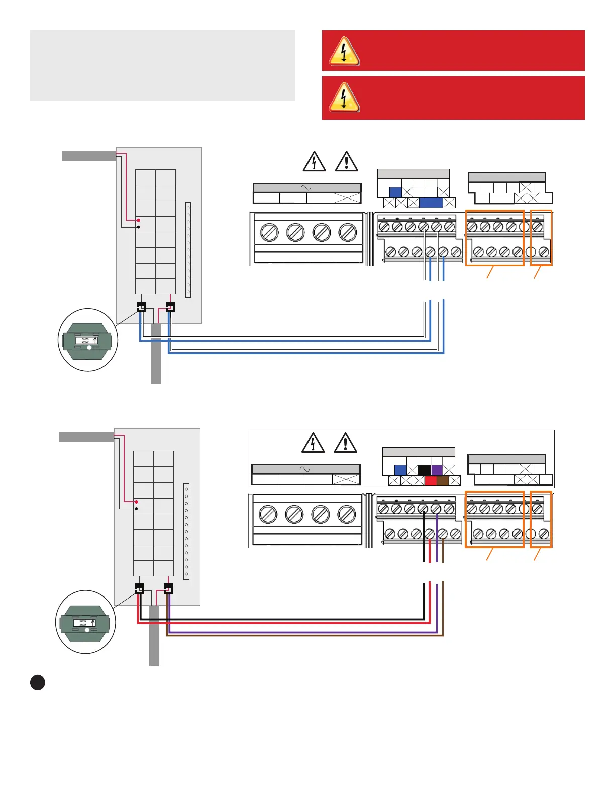
Load Center
To Grid
From IQ Combiner
IQ Gateway Terminal Block
Relay contacts
(if needed)
white
blue
Not used
white
blue
Consumption CTs
The arrows must point
toward the load — away
from the grid.
1 2 3 4
NO
Ref
Common
C
Digital Input Relay
PD, B300
OVC II
L1 L2
N
CU, 75C, 14AWG MIN
MEAS CAT III
OVC III
P1 C1 C2
Production | Consumption
NOTE: It is important to match CT and sense voltage phases.
To properly measure power and energy, CT inputs must align with the
respective voltage inputs. Consistently identify and match the two AC
lines at two points: the main load center feed and the IQ Gateway. Wire
colors (typically black and red) may not always consistently
identify Lines 1 and 2. If in doubt, use a multimeter to check.
DANGER! Risk of electrocution! Do not install CTs when cur-
rent is owing in the sensed circuit. Always install CT wires
in the terminal blocks before energizing the sensed circuit.
DANGER! Risk of electric shock. Always de-energize the
load center before beginning wiring.
Energize and Update the IQ Gateway
A ) Re-install the plastic dead front with the LTE-M1 cell modem
installed on the dead front. Do not completely tighten all of the
screws.
B ) After all screws are partially tightened, go back and tighten each one
completely.
C) Plug in cell modem USB cable into an IQ Gateway USB port
D ) Turn OFF the DG breaker(s).
E ) Reinstall the IQ Combiner 4C door.
F ) Turn on the circuit feeding the combiner.
G ) Log into the Enphase Installer App on your mobile device and down-
load the latest version of IQ Gateway software. To do so, go to the
Settings tab in the Enphase Installer App and select Download Now
under IQ Gateway Software.
7
Load Center
To Grid
From IQ Combiner
IQ Gateway Terminal Block
Relay contacts
(if needed)
purple
brown
Not used
black
red
Consumption CTs
The arrows must point
toward the load — away
from the grid.
1 2 3 4
NO
Ref
Common
C
Digital Input Relay
PD, B300
OVC II
L1 L2
N
CU, 75C, 14AWG MIN
MEAS CAT III
OVC III
P1 C1 C2
Production | Consumption
Figure C: Connection of split-type Consumption CTs
Figure D: Connection of clamp-type Consumption CTs

 Loading...


