4. Warranty Policy & Safety Info
Please register your product with the QR code
below to obtain full warranty benefits, or you
can only get a 2-year warranty.
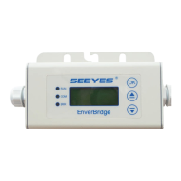
5. WIFI Configuration
a. Connect the network whose name is as same
as your monitor’s SN in your cellphone.
b. Open Envertech and click Wi-Fi Setting.
c. Click to select SSID.
d. Select the WIFI monitor that needs to connect.
e. Enter the password of the selected Wi-
Fi, and finally click the OK button.
Microinverter Safety
*DANGER: Risk of electric shock. Risk of fire. Do
not attempt to repair the Envertech
Microinverter; it contains no user-serviceable
parts. If it fails, contact Envertech customer
service to obtain an RMA (return merchandise
authorization) number and start the replacement
process. Tampering with or opening the
Envertech Microinverter will void the warranty.
*DANGER: Risk of fire. The DC conductors of the
PV module must be labeled “PV Wire” or “PV
Cable” when paired with the Envertech
Microinverter.
*WARNING: You must match the DC operating
voltage range of the PV module with the
allowable input voltage range of the Envertech
Microinverter.
*WARNING: The maximum open circuit voltage
of the PV module must not exceed the specified
maximum input DC voltage of the Envertech
Microinverter. Using electrically incompatible PV
module voids Envertech’s warranty
*WARNING: Risk of equipment damage. Install
the microinverter under the PV module to avoid
direct exposure to rain, UV, and other harmful
weather events. Always install the microinverter
bracket side up. Do not mount the microinverter
upside down. Do not expose the AC or DC
connectors to rain or condensation before
mating the connectors.
*WARNING: Risk of equipment damage. The
Envertech Microinverter is not protected from
damage due to moisture trapped in the cabling
systems. Never mate microinverters to cables
that have been left disconnected and exposed to
wet conditions. This will void the Envertech
warranty.
*WARNING: Risk of equipment damage. The
Envertech Microinverter functions only with a
standard, compatible PV module with
appropriate fill-factor, voltage, and current
ratings. Unsupported devices include smart PV
modules, fuel cells, wind or water turbines, DC
generators, and non-Envertech batteries, etc.
These devices do not behave like standard PV
modules, so operation and compliance is not
guaranteed. These devices may also damage the
Envertech Microinverter by exceeding its
electrical rating, making the system potentially
unsafe.
*WARNING: Risk of skin burn. The chassis of the
Envertech Microinverter is the heat sink. Under
normal operating conditions, the temperature
could be 20°C above ambient, but under extreme
conditions, the microinverter can reach a
temperature of 90°C. To reduce the risk of burns,
use caution when working with microinverters.
*Note: Please do not violate the following
content, otherwise the warranty will be invalid.
1. Ensure that the EVT800 is properly grounded
during installation.
2. It is prohibited to connect more than one
photovoltaic panel to a DC connector.
3. It is prohibited to use batteries and energy
storage products that have not been certified
by Envertech.
Envertech EVT800
Schnellinstallationsanleitung
Bitte lesen und befolgen Sie die folgenden
Sicherheits- und Installationsanweisungen. Sie
können die Anleitungen oder andere technische
Dokumente auf unserer Website
www.envertec.com finden oder scannen Sie den
QR-Code auf der rechten Seite.
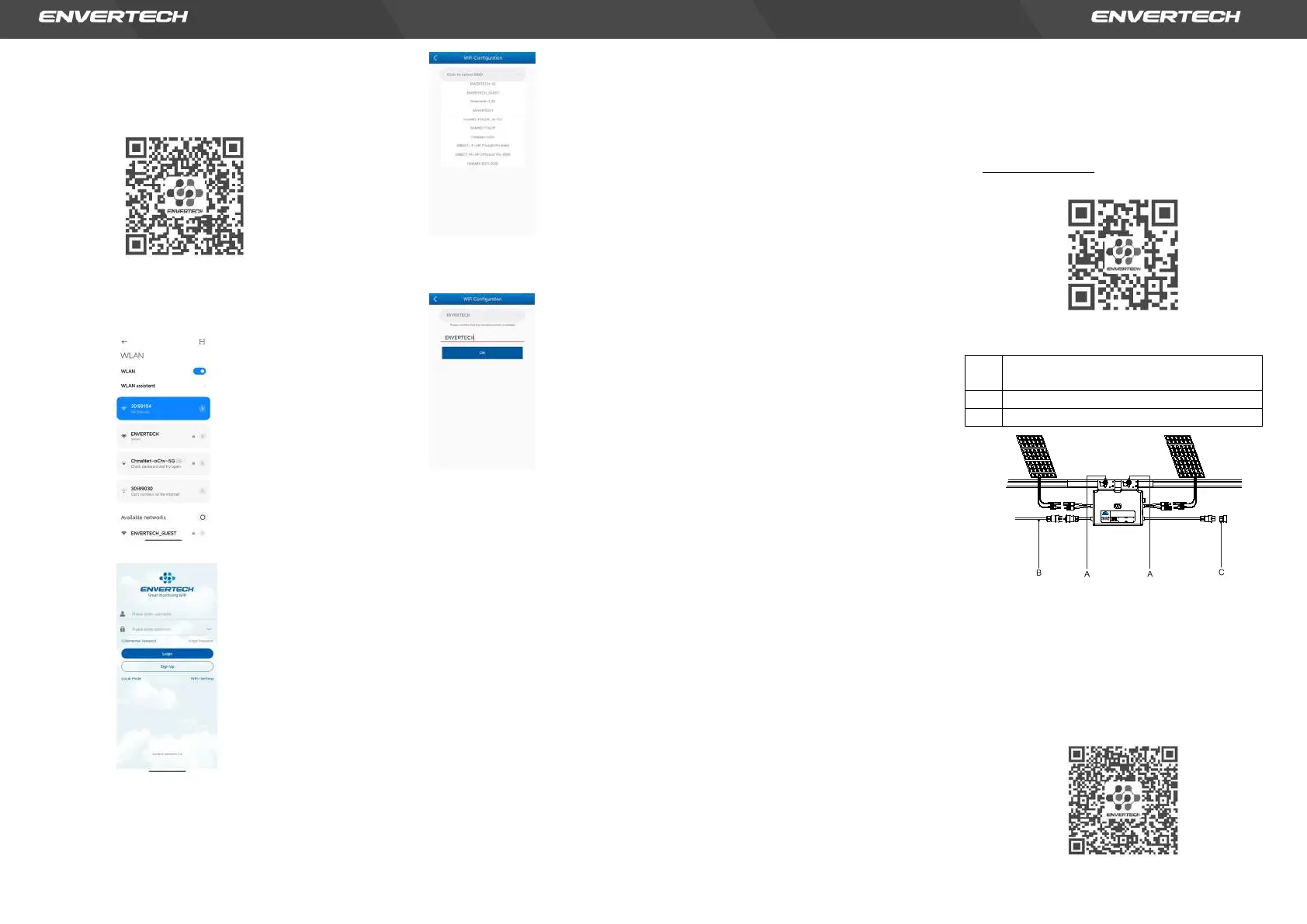
1. Zubehör
M8 x 25 Schrauben (vom Installateur
bereitgestellt)
5 m AC-Verlängerungskabel
12
User IdentificationNumber
Model:EVT800
www.envertec.com
Zhejiang EnvertechCorporationLtd.
PVMicroinverter
OperatingRange(Vdc): 16V~60V NormalVoltage?(Vac): 220/230V
MPPTVoltageRange(Vdc):
Max.DC Input(Vdc):
Max.InputContinuousCurrent?(A):
Max. InputShort-CircuitCurrent(A):
IngressProtection(IP):
Power(Max.Continuous)(W):
Temperature(℃):
22V~48V
60V
14Ax2
25A
IP67
800W
-40℃to+65℃
Current(Max.Continuous)(A):
Frequency?(Hz):
PowerFactorRange:
MaximumUnitsPerBranch:
ProtectiveClass:
OvervoltageCategory:
3.63A
50Hz/60Hz
+/-0.90
7
OVCIII(ACMain),OVC II(PV)
ClassI
*Hinweis: alle oben genannten Zubehörteile sind
nicht im Lieferumfang enthalten und müssen
separat gekauft werden.
2. Ein Installationsplan erstellen
a. Erstellen Sie einen Installationsplan auf Papier,
um die Seriennummern der Mikro-
Wechselrichter und die Position in der Anlage
zu erfassen. Laden Sie das Blatt mit diesem
QR-Code herunter.
 Loading...