ENVIRO-TEC
31
FORM ET115.24-NOM11 (118)
FRBii INPUTS AND OUTPUTS
TB1 – Low Voltage Peripheral Devices
TABLE F.1 – SCREW TERMINAL (TB1) SIGNAL
IDENTIFICATION
(see Table F.9 for detailed description of each signal)
Pin Signal
1
Y1 – Cool 1
2
Y2 – Cool 2
3
W1 – Heat 1
4
L – Low
5
M – Medium
6
H - High
7
G – Fan Enable
8
C – Common (through JP2)
9
C – Common (through JP2)
10
R – 24VAC
11
S2 – Auxiliary Input (Heat 2)
12
S1 – Common
J1 – Low Voltage Peripheral Devices
TABLE F.2 – LOW VOLTAGE PERIPHERAL
DEVICE (J1) SIGNAL IDENTIFICATION
Pin Signal
1
R – 24VAC
2
S2 – Aux In (Heat 2)
3
Y1 – Cool 1
4
Y2 – Cool 2
5
LOW
6
MED
7
HIGH
8
24V
9
24V
10
G – Fan Enable
11
W1 – Heat 1
12
COM
13
DAMP - Damper
14
COM
15
HEAT – Heat output
16
COM
17
24V
18
S1 – Common
J2/J3 – Incoming Power
TABLE F.3 – INCOMING POWER (J2 & J3)
SIGNAL IDENTIFICATION
Pin Signal
1
NEUT
2
120
3
208
4
240
5
277
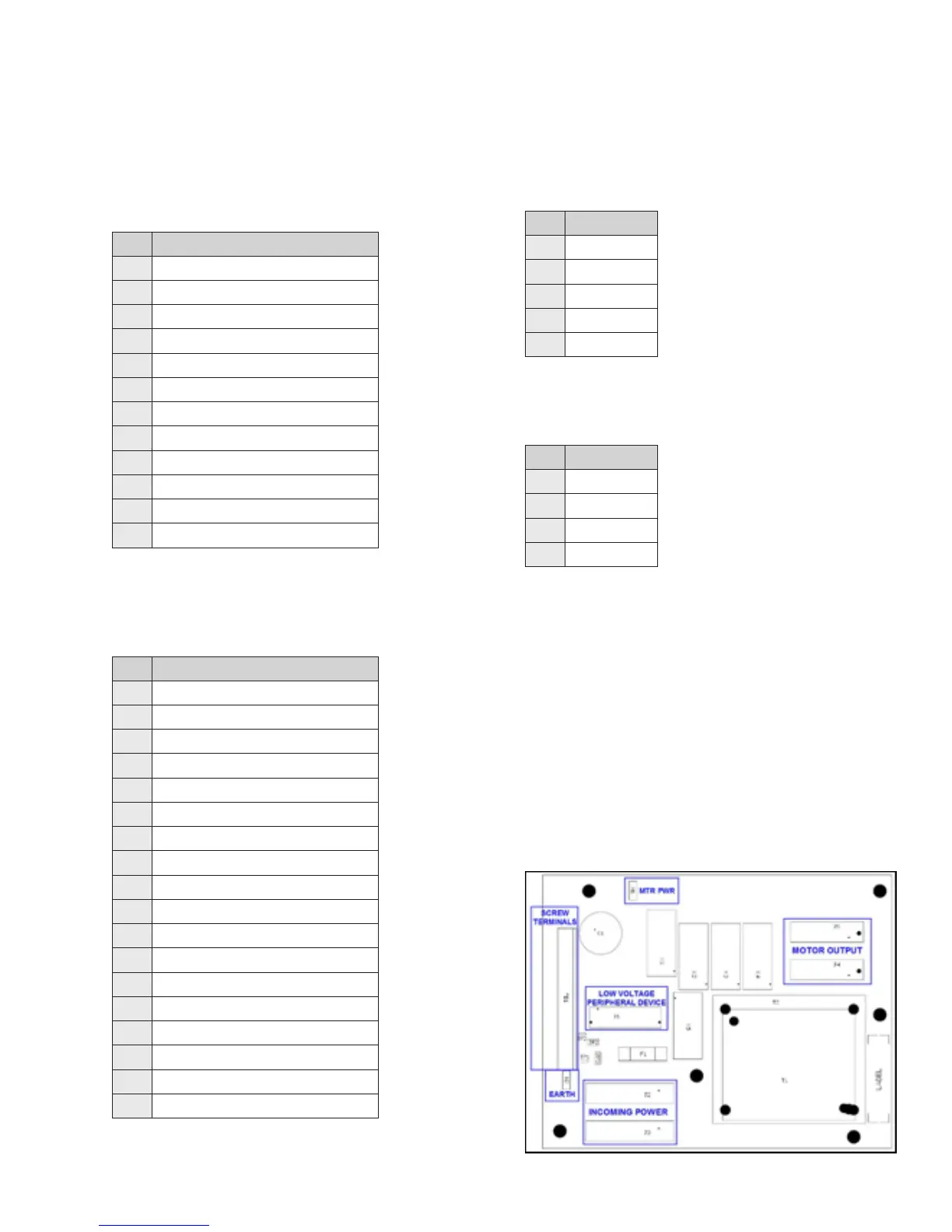
J4/J5 – Motor Output
TABLE F.4 – MOTOR OUTPUT (J4 & J5)
SIGNAL IDENTIFICATION
Pin Signal
1
LOW
2
MED
3
HIGH
4
NEUT
W1 – MTR PWR
The MTR PWR quick connect provides voltage to the
line side of the fan speed relays through an external
jumper. For PSC motors, this will be the line voltage
of the unit. For EC motors, this will either be 24VAC
(without PWM) or a switch contact common (with
PWM).
W2 – EARTH
EARTH connection grounds the secondary side of the
transformer to the enclosure cabinet through a wire
bonded to the control enclosure.
Figure F.2 – Connector layout