ENVIRO-TEC
33
FORM ET115.24-NOM11 (118)
JUMPERS
TABLE F.7 – JUMPER DESCRIPTION
Jumper Name Description
JP1
Speed
Select
Jumper
This jumper is installed between
24V and HIGH when no three
speed switch is included (remote
or unit mounted). The jumper
will be installed at the end of
the harness connected to J1. If a
three speed switch is added later,
JP1 must be removed.
JP2
Float
Switch
Jumper
This jumper is installed between
S1 and C when a oat switch
is not installed. The jumper is
removed when a oat switch is
installed.
JP3
Fan
Enable
Jumper
This jumper is installed between
R and G/24V. The jumper is
removed when remote control of
the fan motor is desired. In most
instances, JP3 will be installed
(unless a thermostat or controller
is remotely controlling of the
equipment).
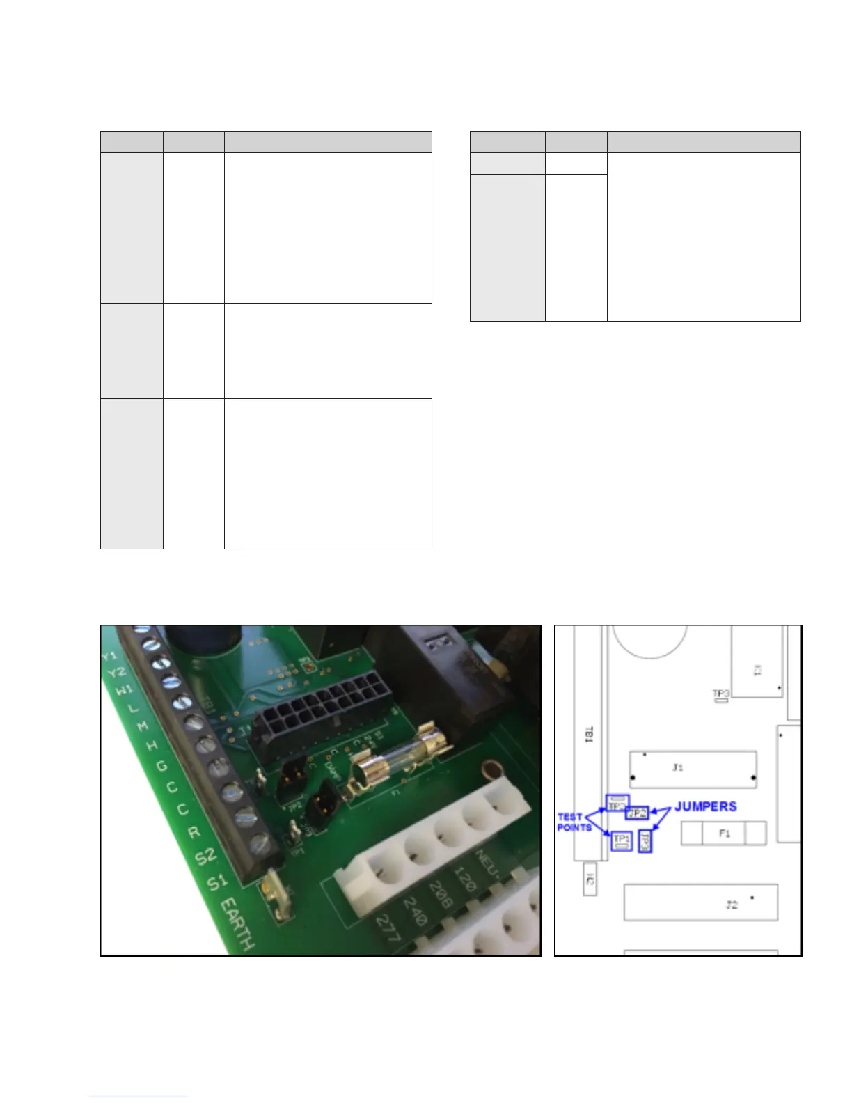
JP2 and JP3 locations can be seen in Figure F.3.
TEST POINTS
TABLE F.8 – TEST POINT DESCRIPTION
Test Point Name Description
TP1
24VAC These test points can be
used to verify 24VAC
assuming incoming voltage
is within tolerance. They
can be connected to with
mini-hook test clips for a
digital multimeter. Test point
locations for TP1 and TP2 can
be seen in Figure F.3.
TP2
COM
Figure F.3: FRBii Jumpers and Test Points