ENVIRO-TEC
16
FORM ET115.24-NOM12 (718)
ELECTRICAL WIRING & CONTROLS
The electrical operation of each unit is determined by
the components and wiring of the unit and may vary
from unit to unit. Consult the wiring diagram for the
actual type and number of controls provided on each
unit. The integrity of all electrical connections should be
veried at least twice during the rst year of operation.
Afterwards, all controls should be inspected regularly
for proper operation. Some components may experience
erratic operation or failure due to age. Wall thermostats
may also become clogged with dust and lint and should
be periodically inspected and cleaned to provide reliable
operation. Please refer to controls manufacturer’s IOM
for periodic maintenance instructions.
When replacing any components such as fuses,
contactors, or relays, use only the exact type, size, and
voltage component as furnished from the factory. Any
deviation without factory authorization could result in
personnel injury or damage to the unit and will void all
factory warranties and listings. All repair work should
be done in such a manner as to maintain the equipment
in compliance with governing codes and ordinances or
testing agency listings.
More specific information regarding the use and
operating characteristics of the standard controls offered
by this manufacturer is contained in other manuals.
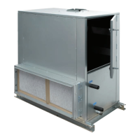
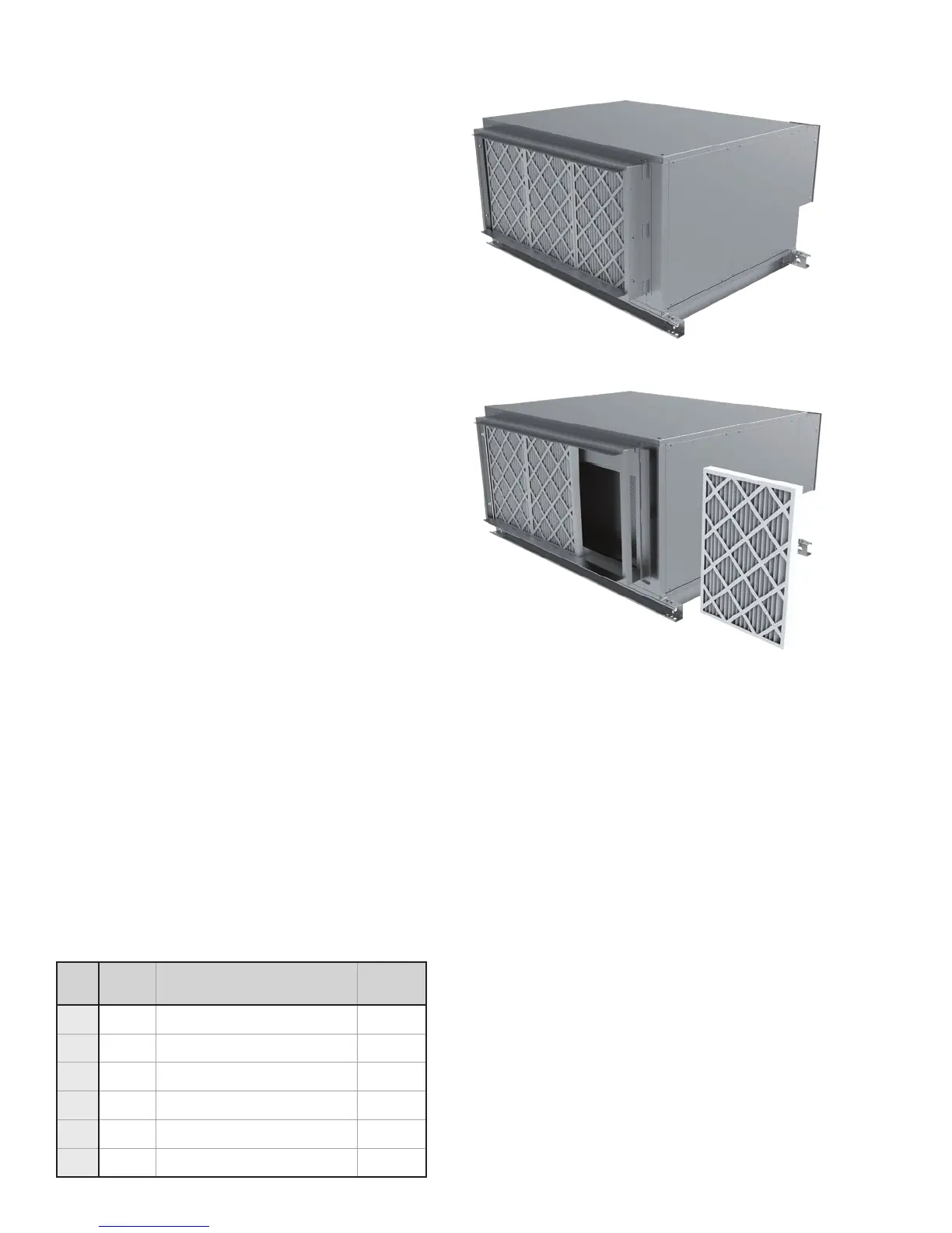
FILTERS, THROWAWAY
The type of throwaway lter most commonly used on
blower-coil units should be replaced on a regular basis.
The time interval between each replacement should be
established based on regular inspection of the lter and
should be recorded in the log for each unit. Refer to the
chart below for recommended lter size for each product
type and size. If the replacement lters are not purchased
from the factory, the lters used should be the same type
and size as that furnished from or recommended by the
factory. Consult the factory for applications using lter
types other than the factory standard or optional product.
Figure 7a-7b: Filter removal
Figure 7a
Figure 7b
TABLE 3: FACE AREA, FREE AREA & FILTER SIZES
UNIT
SIZE
COIL
FACE
AREA
2" FLAT FILTERS
(QUANTITY) & SIZE
FILTER
FACE
AREA
08 2.1 [0.20]
(1) 15.75 x 19.75 x 2
[400 x 502 x 51]
2.2 [0.20]
12 2.7 [0.25]
(1) 15.75 x 24.75 x 2
[400 x 629 x 51]
2.7 [0.25]
16 3.5 [0.33]
(2) 15.75 x 19.75 x 2
[400 x 502 x 51]
4.3 [0.40]
20 4.9 [0.46]
(1) 15.75 x 19.75 x 2 [400 x 502 x 51]
(1) 15.75 x 24.75 x 2 [400 x 629 x 51]
4.9 [0.46]
30 6.5 [0.60]
(2) 24.75 x 15.75 x 2 [629 x 400 x 51]
(1) 24.75 x 19.75 x 2 [629 x 502 x 51]
8.8 [0.82]
40 8.4 [0.78]
(3) 24.75 x 19.75 x 2
[629 x 502 x 51]
10.2 [0.95]
NOTES:
1. Standard lters are 2" throwaway.
2. Filter sizes are nominal and standard size, measure in
inches [millimeters].
3. Coil and lter face areas are measured in square feet
[square meters].
4. Cooling and heating coils have same face area.