ENVIRO-TEC
4
FORM ET115.24-NOM12 (718)
During and after installation, special care must be taken
to prevent foreign material such as paint, plaster, and
drywall dust from being deposited in the drain pan, coil,
or on the motor or blower wheels. Failure to do so may
have serious adverse effects on unit operation and in
the case of the motor and blower assembly, may result
in immediate or premature failure. All manufacturers’
warranties are void if foreign material is allowed to be
deposited on the motor or blower wheels of any unit.
Some units and/or job conditions may require some form
of temporary covering during construction.
While the manufacturer does not become involved
in the design and selection of support methods and
components, it should be noted that unacceptable
system operating characteristics and/or performance
may result from improper or inadequate unit structural
support. In addition, adequate clearance must be
provided for service and removal of the equipment and
its accessory components. Anchoring the equipment in
place is accomplished by using the mounting points
provided and positioning the unit to maintain the unit
on a LEVEL plane. The drain pan is internally sloped
toward the outlet connection. Care must be taken to
insure that the unit drain pan does not slope away from
the outlet connection.
The unit’s drain pan is factory sloped
toward the drain connection when the
unit is installed level and plumb.
UNIT RIGGING AND PLACEMENT
Install ductwork to comply with ASHRAE Fundamentals
Handbook, SMACNA, NFPA 90A and local code.
The installation must conform with local building codes
and the National Electric Code.
Locate unit support in accordance with the mechanical
and structural plans. If so equipped, locate the isolator
placement and correct size as shown on the submittal
drawing.
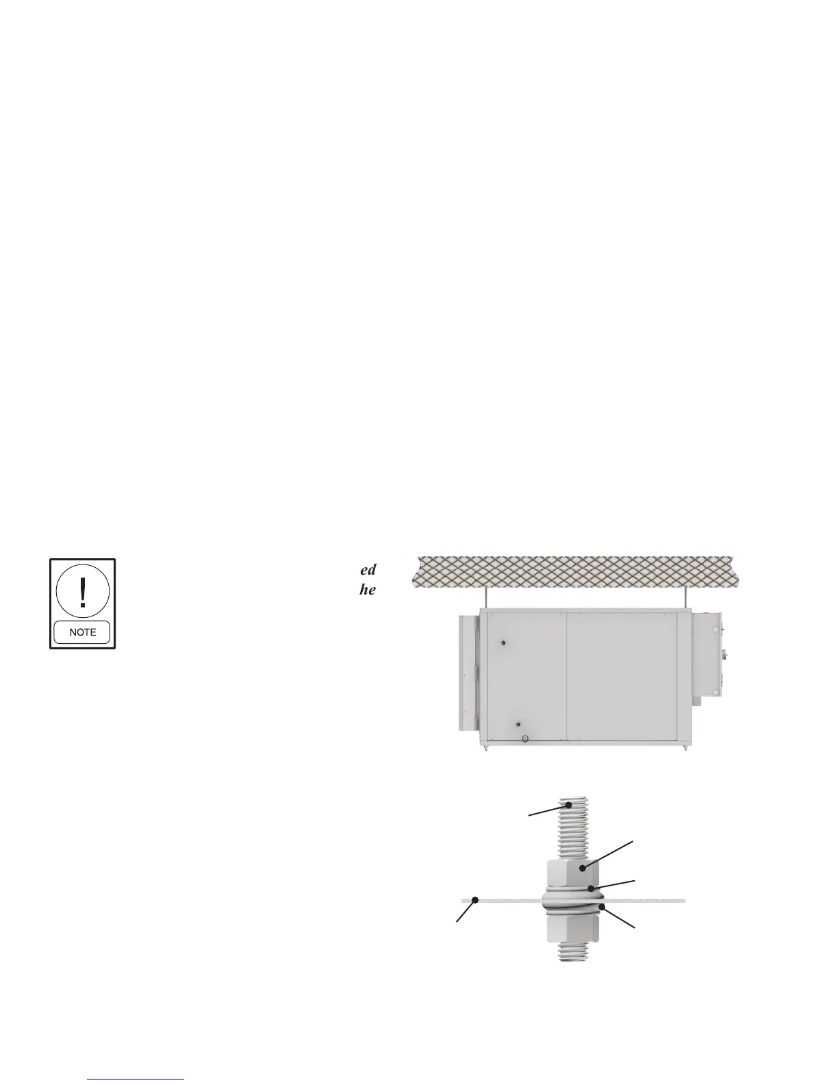
Ceiling suspension of horizontal units have factory
provisions for thru bolt hanger rods. If oor mount
isolators are required for either horizontal or vertical
units, then factory or eld provisions must be made
for isolator attachment. Vertical units can be mounted
directly to the oor or on a base rail. For units with
isolators but no base rail, 6" legs are required and will
need to be mounted to the base of the unit. If a base rail
is provided, isolators can be installed in mounting holes
provided on this base rail.
Do not handle the unit using coil stubout connectors, as
damage may occur at brazed joint(s).
Threaded rod
Nut
Washer
Optional
vibration
isolator
Unit
Figure 1a-1b: Typical ceiling installation
Figure 1a: Side view
Figure 1b: Installation detail