ONE STAGE LIGHT OIL BURNERS
9 / ...
000608....._2006/09
INSTALLING ON BOYLER
N° 0002932940
Rev. 04/10/99
CAUTION: when attaching the burner to the flange position the combustion head axis as illustrated in the
diagram (angle α).
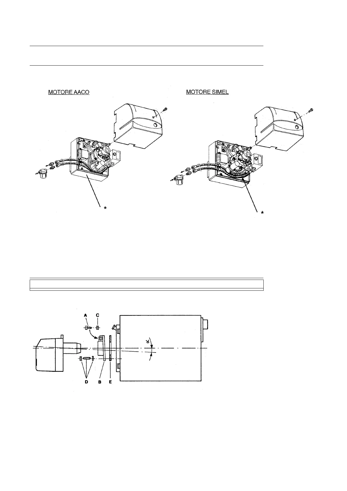
DIAGRAM SHOWING HOW TO PLACE THE FLEXIBLE PIPES
N° 0002933210
Rev. 22/09/00
* The two flexibles hoses shall be positioned as show on the figure for ensuring correct closing of the cover,
they can come out from the lower side or the left side of the burner.
WITH SLIDING FLANGE:
- Fasten flange (B) to the boiler with n°4
screws (D) placing the insulation card
(E);
- Insert burner into flange / boiler and
tighten screw (A) with nut (C).