EasyManua.ls Logo

EOGB X500 User Manual

EOGB X500
44 pages
To Next Page IconTo Next Page
Page #1 background imageLoading...
Page #1 background image
Revision 1 01/01/16
INSTRUCTION MANUAL FOR OIL BURNER MODELS
X400 14-36 kW
X500 34-62 kW
X600 50-80 kW
ONE STAGE, GAS OIL, KEROSENE AND B10 BIOFUEL BURNERS
The X-series range is available in three models, with outputs ranging from 14 to 80
kW, They can be congured for conventional or ducted air inlets to suit installations
in domestic. commercial and light industrial premises. All the models are approved
by the EN267 European Standard and conform to European Directives for EMC, Low
Voltage, Machinery and Boiler Eciency.

Table of Contents

Question and Answer IconNeed help?

Do you have a question about the EOGB X500 and is the answer not in the manual?

EOGB X500 Specifications

General IconGeneral
BrandEOGB
ModelX500
CategoryBurner
LanguageEnglish

Summary

Declaration

Declaration of Conformity

Formal statement of compliance with EU directives and standards for EOGB products.

Information and General Warnings

Manual Introduction and Safety Symbols

Explains the manual's purpose, its integral nature, and general safety symbols.

General Danger Levels Explained

Details the three levels of danger symbols (DANGER, WARNING, CAUTION) and their meanings.

Live Component Electrical Dangers

Highlights risks associated with electrical components and the need for caution.

Environmental Protection Symbol

Indicates the symbol for machine use respecting the environment.

Guarantee and Responsibility

Biofuel Blend Usage Guidance

General Instructions for Biofuel Use

Product Disclaimer Statement

Safety and Prevention

Introduction to Safety and Dangers

Emphasizes safety in burner design and potential dangers from misuse.

Safety Warnings and Basic Rules

Lists essential safety warnings, basic rules, and precautions for operation.

Personnel Training and Responsibilities

Defines user responsibilities and the need for qualified personnel for safe operation.

Technical Description of the Burner

Burner Technical Data Summary

Presents key specifications including heat output, weight, fuel data, and electrical details.

Burner Components Identification

Included Burner Accessories

Burner Dimensions and Specifications

Burner Firing Rates and Performance

Installation Procedures

Safety Notes for Installation

Emphasizes safe practices during burner installation, including electrical disconnection.

Safe Handling of the Burner Unit

Provides guidance on safely handling the burner unit during installation.

Preliminary Checks Before Installation

Details checks for consignment integrity and burner identification labels.

Biofuel Blend Installation Notes

Burner Working Position Guidelines

Boiler Mounting and Fixing

Service Mounting Position Feature

Air Intake Assembly and Configurations

Balanced Flue Requirements

Oil Pump System

Pump Priming Procedures

Explains how to prime the oil pump for both 1-pipe and 2-pipe systems.

Oil Supply System Configuration

Oil Supply Pipework Guidelines

Electrical System

Notes on Electrical Wiring Safety

Emphasizes safety precautions and compliance for electrical wiring operations.

X400 & X500 Electrical Wiring (No 7 Pin Plug)

Worcester Boiler Harness Wiring

X500 & X600 Wiring (With 7 Pin Plug)

Burner Operation and Commissioning

First Start-Up Safety Procedures

Outlines essential safety checks and procedures for the initial burner start-up.

Combustion Adjustment Procedures

Details how to adjust combustion for optimal efficiency using CO2 levels and flue gas analysis.

Burner Combustion Adjustment Details

Pump Pressure Settings

Nozzle Installation and Selection

Air Damper Adjustment for Output

Electrode Setting Specifications

Burner Start Cycle Overview

Maintenance and Service

Safety Precautions for Maintenance

Lists critical safety steps before performing any maintenance or cleaning.

Recommended Maintenance Schedule

Outlines periodic checks for Kerosene and Gas Oil based on usage frequency.

Component Checking and Cleaning

Details procedures for checking and cleaning combustion head, burner, fan, photocell, electrodes, nozzles, filters, and pump.

Burner Fault Finding Guide

Commissioning Report Sheet

Service Records Log

Spare Parts List - X400

X400 Spare Parts Identification

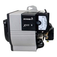
Lists and visually identifies spare parts for the X400 model with item numbers.

X500 Spare Parts Identification

X500 Spare Parts List Details

X500 Spare Parts List Details (Cont.)

X500 Spare Parts List Details (Cont.)

X600 Spare Parts Identification

X600 Spare Parts List Details

X600 Spare Parts List Details (Cont.)

Manual Notes and Contact Information

General Notes Section

General notes section indicating further information may be available.

Related product manuals