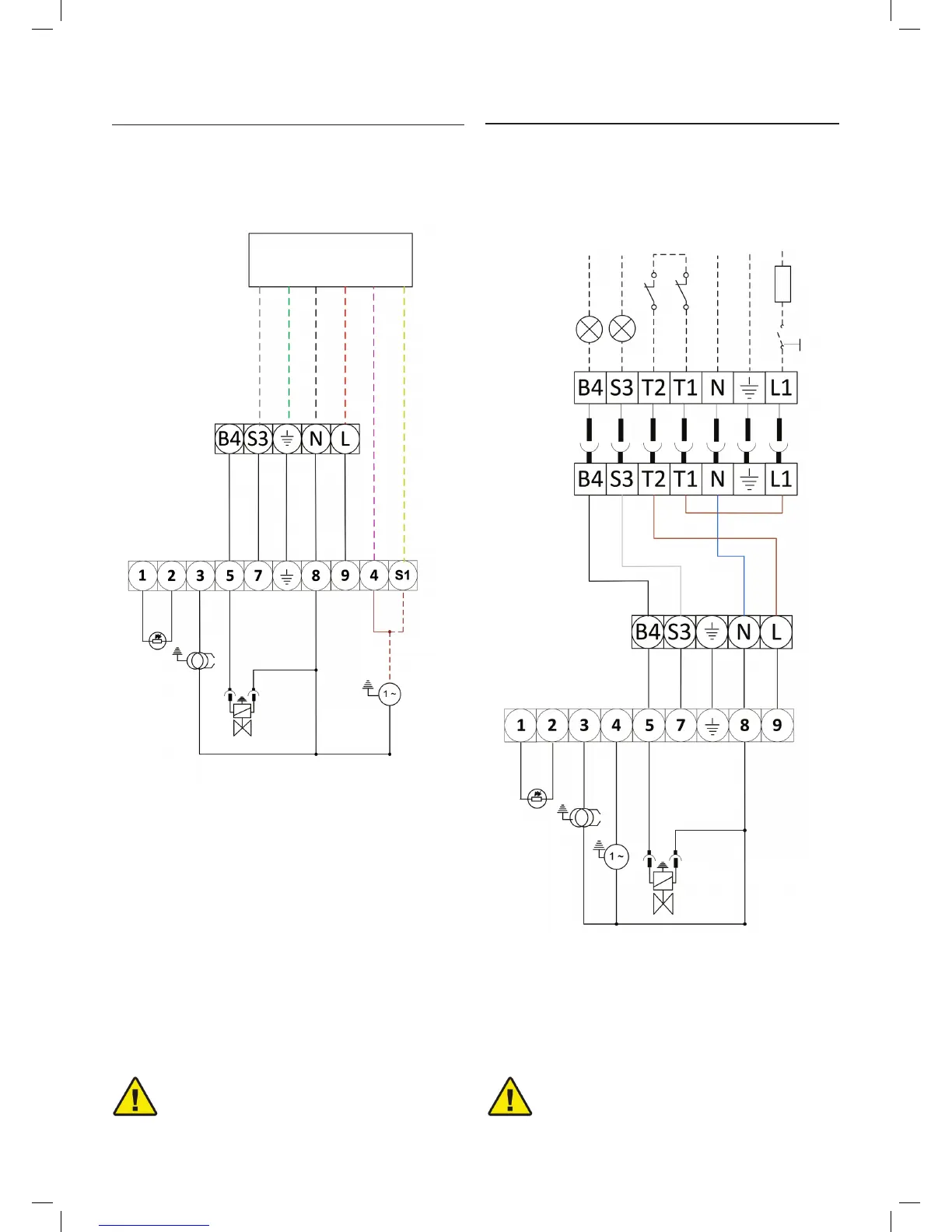
7.2.3 Worcester Boiler Harness Electrical Wiring
Electrical System
With many Worcester boilers, the wiring harness will have 6
wires in total. If you have this version then please follow the
following diagram.
Worcester Wiring
Harness
* remove motor lead wire from T4 and t into S1 with
yellow from harness
*
Grey
Earth
Black
Red
Pink
Yellow
Brown
7.2.4 X500 & X600 wiring (with 7 pin plug)
Components
A1 - Satronic S98 Wiring Base
PE - Photocell
T - Transformer
M - Motor
V1 - Solenoid Valve
X3 - 5 Pin Terminal Strip
B1 - Worcester Wiring Harness
If the X-Series has been supplied with a 7 pin plug, then
please follow the below wiring diagram.
A1
PE
T
M
V1
X3
B1
Internal Components
A1 - Satronic S98 Wiring Base
PE - Photocell
T - Transformer
M - Motor
V1 - Solenoid Valve
X3 - 5 Pin Terminal Strip
External Components
S1 - Isolation Switch
F - Fuse (5 amp)
TC - Control thermostat
TS - Limit Thermostat
H1 - Lockout indicator
H2 - Burner Run Indicator
A1
PE
T
M
V1
X3
S1
F
TC
TS
H1
H2
Earth
Neutral
Live
1 ph 230v - 50Hz
TESTING:
Check the shut-down of the burner by opening
the thermostats and the lock-out by darkening
the photo-resistance.
WARNING
TESTING:
Check the shut-down of the burner by opening
the thermostats and the lock-out by darkening
the photo-resistance.
WARNING
Fig. 17
Fig. 18