Electrical System
7.2.1 Electrical wiring
This operation must be performed by a qualied
engineer with the boiler turned o and mains
power disconnected.
Do not swap neutral and phase over, follow the di-
agram shown carefully and ensure their is a good
earth connection
The electrical wiring carried out by the installer
must be in compliance with the rules in force in
the country.
The section of the conductors must be at least
1mm2 (unless requested otherwise by local stand-
ards and legislation).
DANGER
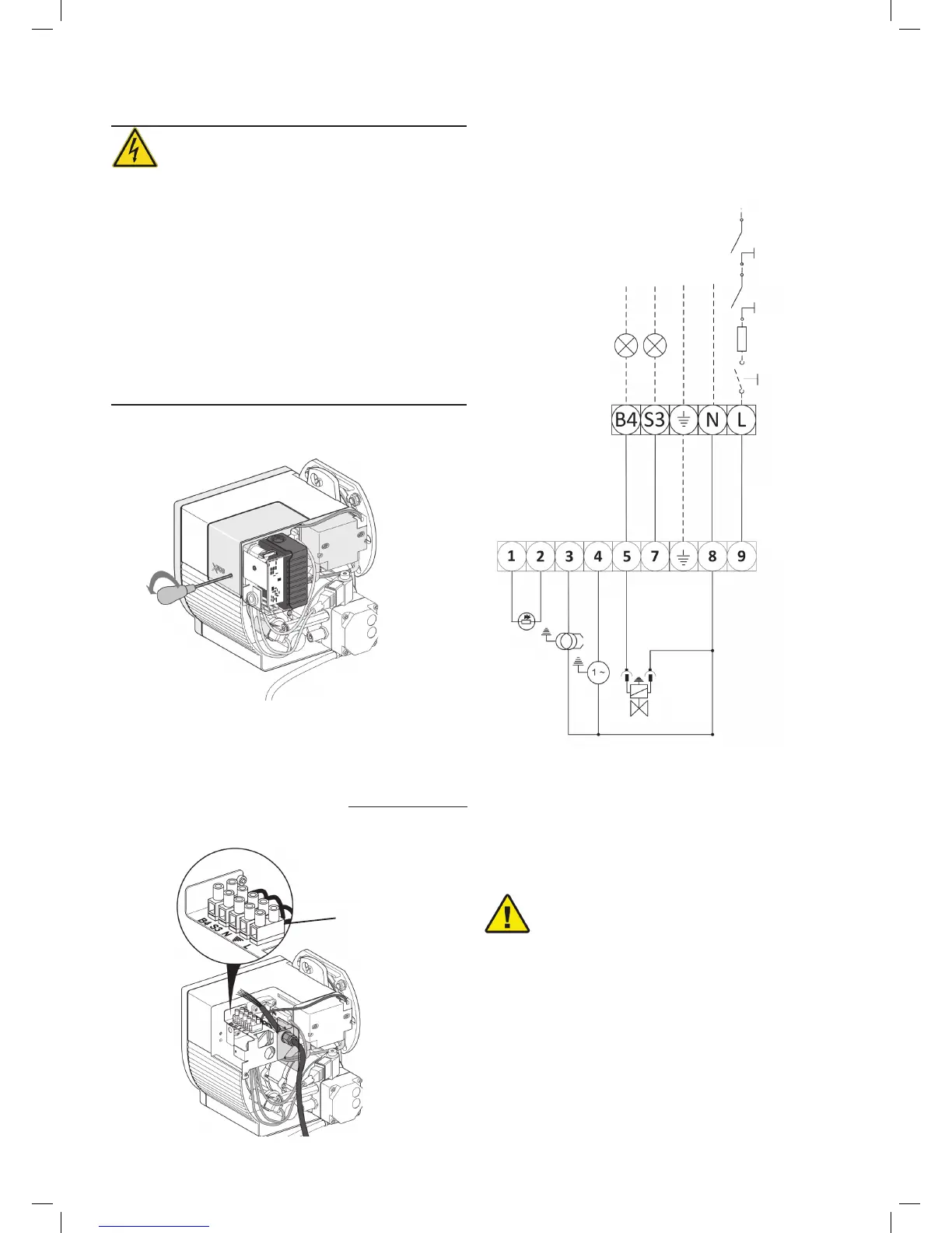
If tting the X400 or X500 then before carrying out any elec-
trical wiring, the electronics cover must be removed (see Fig
18 & 19)
Internal Components
A1 - Satronic S98 Wiring Base
PE - Photocell
T - Transformer
M - Motor
V1 - Solenoid Valve
X3 - 5 Pin Terminal Strip
A1
PE
T
M
H1H2
Neutral
Earth
Live
1 ph 230v - 50Hz
S1
F
TC
TS
V1
X3
X3
Once the cover has been removed then all wiring can be
wired into the 5 pin terminal strip (X3 on Fig 19) please see
wiring diagram for further information.
If the X-series burner is being tted to a WORCESTER BOILER
that has 6 wires then please follow instructions given in sec-
tion 7.2.3
Fig. 14
Fig. 15
External Components
S1 - Isolation Switch
F - Fuse (5 amp)
TC - Control thermostat
TS - Limit Thermostat
H1 - Lockout indicator
H2 - Burner Run Indicator
TESTING:
Check the shut-down of the burner by opening
the thermostats and the lock-out by darkening
the photo-resistance.
WARNING
Wiring Diagram for X400 & X500
(without 7pin connections)
7.2.2 X400 & X500 Electrical wiring (No 7 pin plug)
Fig. 16