5.7 Air intake assembly
5.7.1 Conventional Flue Applications (CF)
5.7.2 Balanced Flue Applications (BF)
In case of CF applications, the burner would not need to
be amended.
The temperature of the incoming air must
not exceed 70 °C.
For correct BF application, the burner must be
installed on an appropriate BF boiler.
In case of BF applications an optional air intake is supplied
with the X400. see Fig. 7
The X500 and X600 both have the BF air intake tted as
standard.
WARNING
CAUTION
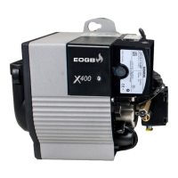
An additional rubber adaptor is also supplied with the X400
and X500 models in the accessory kit (if required) and will
convert the standard 60mm air intake tting to a 70mm
tting. see Fig. 8
(Please note that the X600 has a 70mm air intake as stand-
ard and therefore does not have a adaptor supplied)
Installation
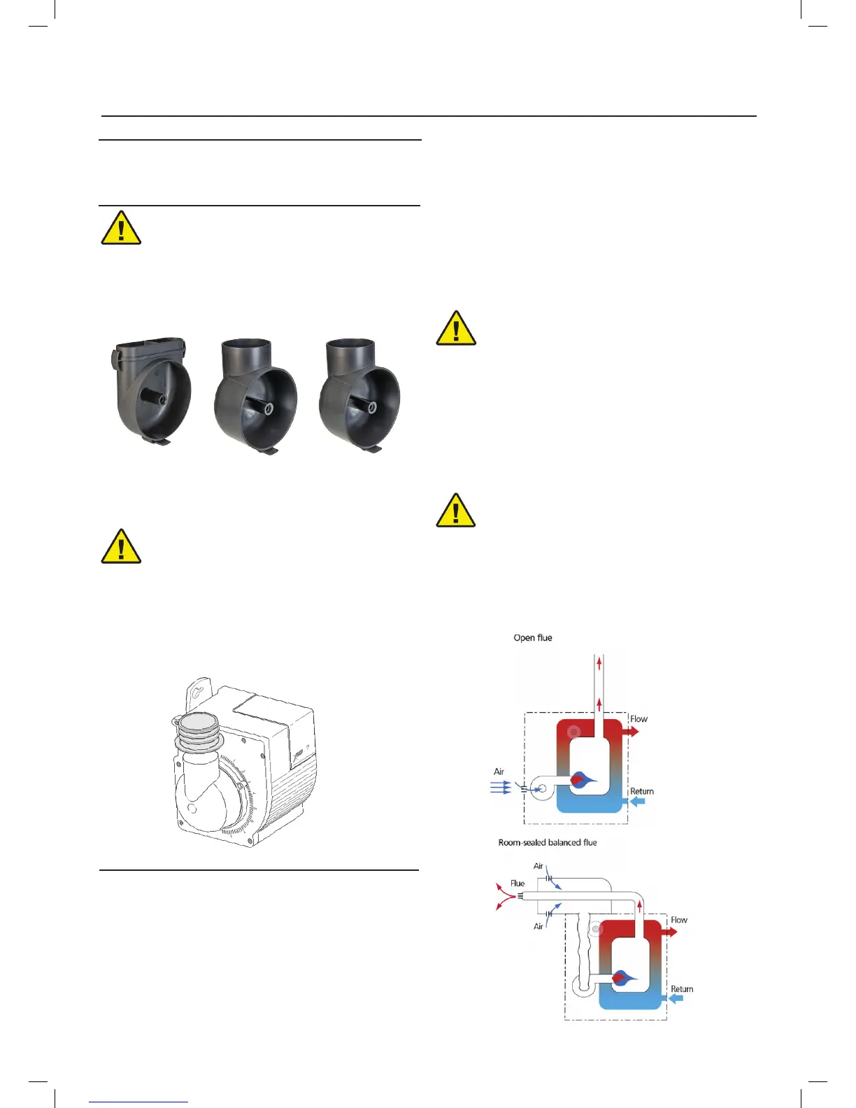
Fig. 7
X400 standard
air intake
X500 standard
60mm air intake.
(also supplied in
the X400 air intake
conversion kit)
X600 standard
70mm air intake
Fig. 8
5.7.3 Balanced Flue Requirements
The combustion air supply is through a exible or rigid pipe
connected to the air intake.
Consequently, you must comply with the following require-
ments and instructions:
The combustion air intake tube must be:
• fastened securely to the burner;
• made of a suitable material, with
temperature characteristics in the range - 30 °C to
80 °C;
• in compliance with all requirements of applicable
regulations in force in the country of destination.
• The intake-tube / burner system must not allow
a loss of over 2 m3/h at 0.5 mbar: for instance, the
above requirements will be met if you use ues for pressure
exhaust of ue gases (the condensation kind).
• Make sure the air intake tube’s inlet is positioned
so that it is not likely to be obstructed by foreign matter
and, where necessary, use suitable screens.
• The inside diameter of the hose must be at least
80 mm.
• The intake tube can be up to 6 metres in length.
Length is reduced if there are bends in the intake
section.
For instance, if using a tube with a smooth inside
surface, you must allow for the following losses:
– for each 45° bend, tube length is
reduced by 0.5 m;
– for each 90° bend, tube length is
reduced by 0.8 m.
NOTE:
Burner installation must comply with one of the installations
illustrated in the gures 9 & 10
• Under no circumstances should the air’s
entry in the hose intake area be
obstructed.
• The hose must not be blocked in any
way or feature a shutting device
(valves, membranes etc.).
• Coaxial tubes must not be installed for
any reason
WARNING
WARNING
Fig. 9
Fig. 10