Oil Supply
6.2 Oil Supply
(See Fig.17).
Plastic or steel tanks should be installed to BS5410.
A steel tank should also conform to BS799: part 5 and be
arranged with a slope of 1 in 24 away from the outlet valve
with a sludge cock at its lower end.
Do not use galvanised steel tanks or pipework for the oil
supply system.
Do not use soldered joints in the oil supply pipework as this
could cause a hazard in the case of a re.
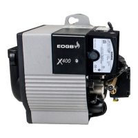
All X-Series burners are supplied and congured to be con-
nected to a single pipe gravity feed system. Details of how
to convert the burners to a 2 pipe sub-gravity feed system
are shown in Fig. 15
6.3 Oil Supply System
(Fig. 13 a) 1 Pipe System
If a single pipe system is employed, then the tank must be
positioned such that the oil level does not exceed 4 metres
above the level of the burner oil pump and in addition the
oil level must be at least 0.3 metres above the level of the oil
pump. Should it prove impossible to site the tank below the
4 metres maximum oil level, a head breaking device must
be installed between the tank and the burner.
(Fig. 13 b) 2 Pipe System
If a 2 pipe system is used then the maximum suction height
allowable is 3.5 metres.
(Fig. 13 c) 1 Pipe Suction Li with De-aerator
If a single pipe suction li with a de-aerator is used, the oil
tank must be positioned below the burner. An inlet and
return loop should be created between the de-aerator
and oil pump. The oil pump should be connected as for a
2 pipe system. Details of how to convert to a 2 pipe system
are shown in Fig. 13.
Oil inlet and return exible hoses should be connected to
the oil pump inlet and return ports.
Table D is a general guide to determine the maximum
allowable pipe run when using a de-aerator.
Table D does not override the de-aerators manufacturer’s
instructions and should only be used in conjunction with
the manufacturer’s instructions.
If a non-return valve is not incorporated within the de-aer-
ator unit, a non-return valve should be tted in the oil line
between the oil tank and the de-aerator.
NOTE: If a de-aerator is used it should be tted externally to
the building (with exception to specic internally version in
which would have to be vented to the outside).
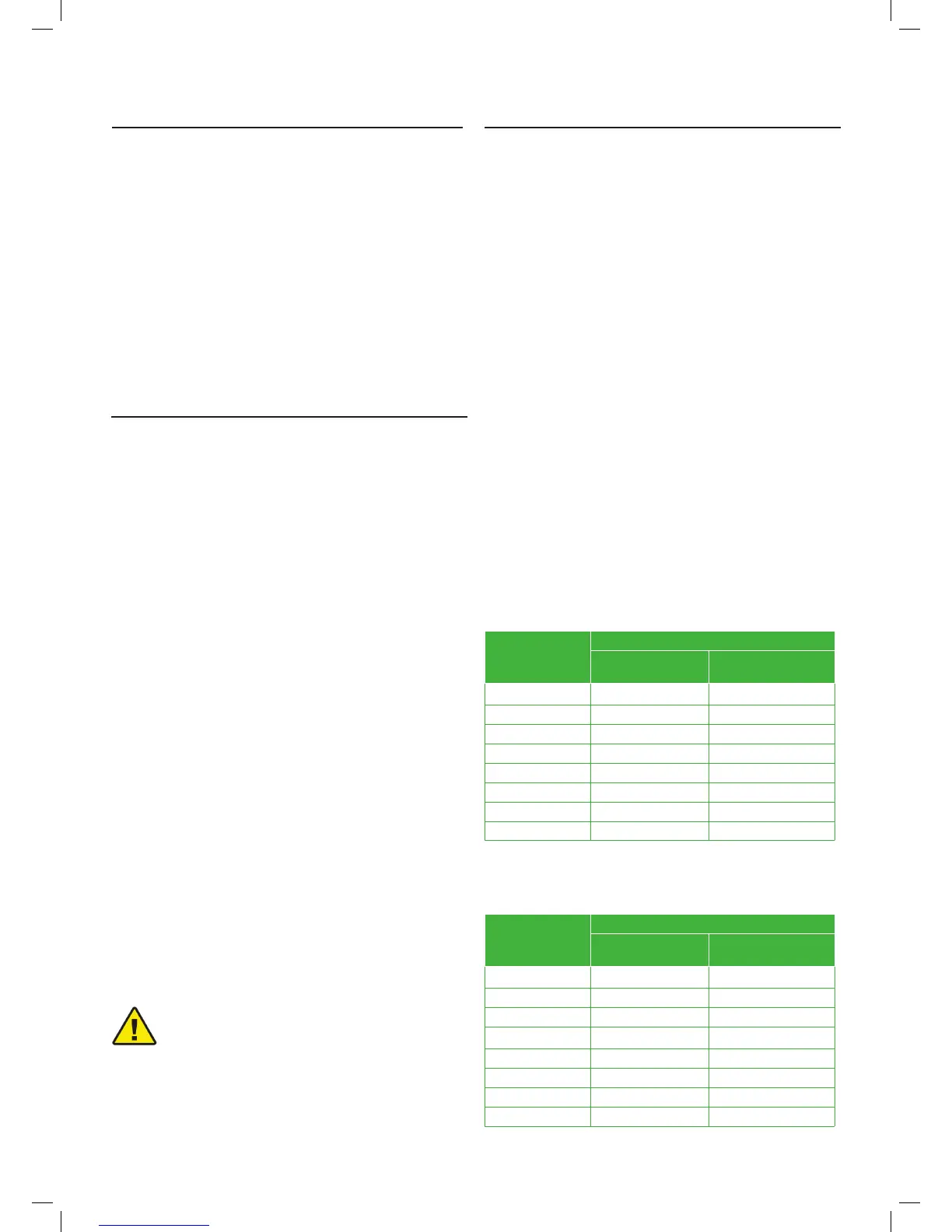
Table. B - 1 Pipe Gravity Feed System
6.4 Oil Supply Pipework
HEAD (metres)
Maximum Allowable Pipe Run (metres)
8mm inside dia pipe
(10mm OD copper)
10mm inside dia pipe
(12mm OD copper)
0.5 12 30
1.0 25 69
1.5 37 91
2.0 49 100
2.5 62 100
3.0 74 100
3.4 87 100
4.0 99 100
HEAD (metres)
Maximum Allowable Pipe Run (metres)
8mm inside dia pipe
(10mm OD copper)
10mm inside dia pipe
(12mm OD copper)
-.5 12 30
-.0 25 69
-.5 37 91
2.0 49 100
2.5 62 100
3.0 74 100
3.4 87 100
4.0 99 100
Table. C - 2 Pipe Sub-Gravity Feed System
a) The oil supply pipe diameter can be determined using
Tables B, C and D depending on whether a 1 or 2 pipe sys-
tem or 1 pipe suction li system is being installed. Selection
of the correct pipe diameter will depend on the position of
the oil storage tank relative to the burner and the length of
pipe run.
b) The oil supply pipe should be laid as level as possible to
avoid air pockets and unnecessary friction losses.
c) The following components should be tted in the fuel line
between the storage tank and burner:
1. A manual isolating valve installed as close to the
tank as possible.
2. A re valve in accordance with BS5410, Part 1 as
shown in Fig 17. The re valve should be tted externally with
a re detection element located within the appliance case.
Use of a capillary type valve will allow a neat and simple
installation. A suitable valve is the KBB manufactured by
Teddington Controls Limited.
3. An oil lter should be tted close to the oil storage tank. If
there is doubt about the internal oil line condition, a further
lter should be tted near the boiler.
You are advised to use additional lters on the fuel
supply line. It is recommended that a good quality
fuel lter at the tank (Fig. 13) and a secondary
lter (60 µ for gas oil and 15 µ for kerosene) are
used to protect the burner pump and nozzle from
contamination.
In case of biodiesel use, pay attention to install
compatible lters. (Contact EOGB for more infor-
mation)
CAUTION