0
0.5
1
1.5
2
2.5
3
3.5
4
4.5
5
0 1 2 3 4 5 6 7 8
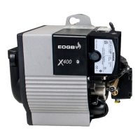
Technical description of the burner
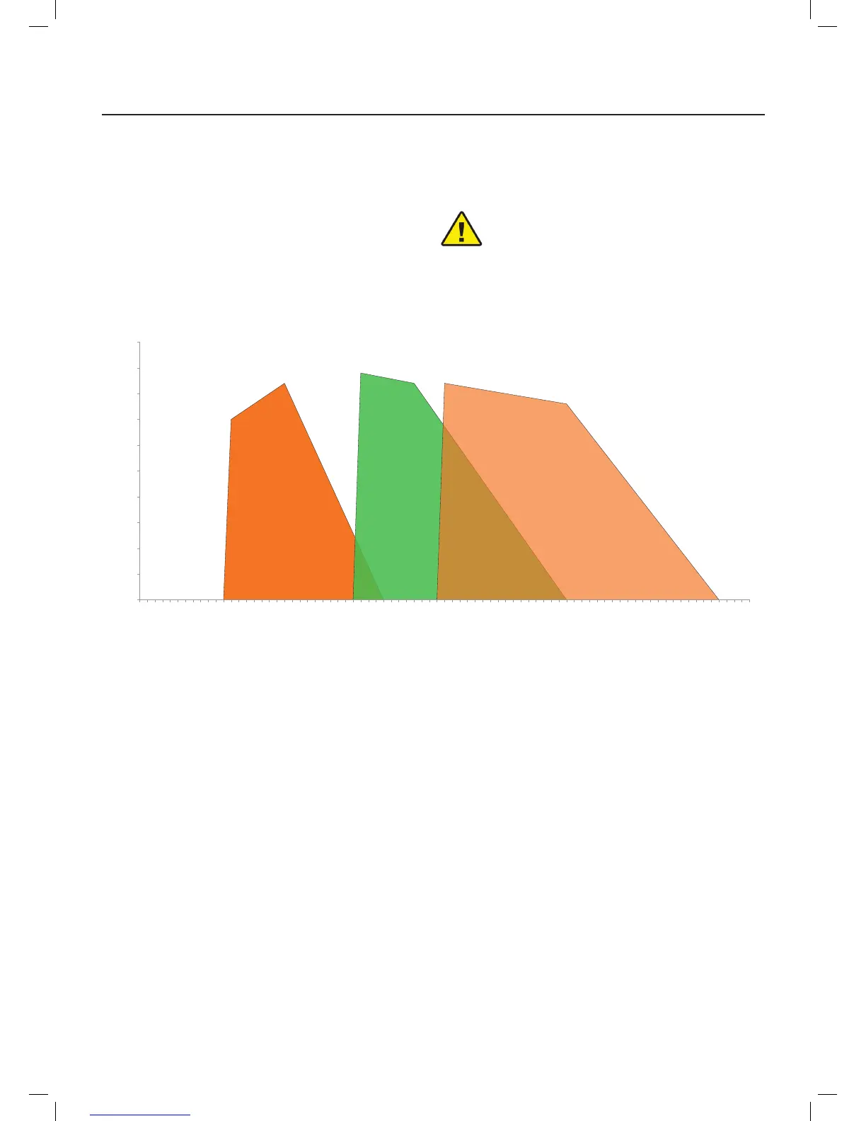
4.5 Firing rates
The MAXIMUM OUTPUT is chosen from within the diagram
area (Fig. 3).
The MINIMUM OUTPUT must not be lower than the minimum
limit of the diagram.
The burner delivery must be selected within area of the
diagrams (Fig. 3). This area is called ring rates and pro-
vides the maximum delivery of the burner in relation to the
pressure in the combustion chamber.
The work point may be found by plotting a vertical line from
the desired delivery and a horizontal line from the pressure
in the combustion chamber. The intersection of these two
lines is the work point which must lie within the ring rates.
The ring rate area values have been obtained
using Class C2 Kerosene and considering a
surrounding temperature of 20 °C, and an at-
mospheric pressure of 1013 mbar (approx. 0 m
above sea level) and with the combustion head
adjusted to factory settings
WARNING
Fig. 3
Kg/h
Combustion chamber pressure (Mbar)
X400 X500 X600