Burner Operation and Commissioning
8 Burner Operation and Commissioning
8.1 Notes on safety for the rst start-up.
The rst start-up of the burner must be carried
out by qualied personnel, as indicated in this
manual and in compliance with the standards/
regulations and local authority legislation
Check the correct working of the adjustment,
command and safety devices.
WARNING
WARNING
In conformity with Eciency Directive 92/42/EEC the
application of the burner on the boiler, adjustment and
testing must be carried out observing the instruction
manual of the boiler, including verication of the CO and
CO2 concentration in the ue gases, their temperatures and
the average temperature of the water in the boiler.
8.2 Combustion adjustment
Combustion air is drawn in from outside, mean-
ing there may be notable changes in tempera-
ture, which can aect the percentage of CO2.
You are advised to adjust CO2 in accordance
with the graph featured.
Example: outside air temperature 10 °C, adjust
CO2 to 11.6% (± 0.2%).
A CO level should be kept to a minimum and
ideally less than 100ppm but if in doubt then
contact EOGB.
WARNING
% CO²
Outside Air Temperature (°C)
Fig. 19
8.5 Nozzles installation
The burner complies with the emission requirements of the
EN 267 standard.
In order to guarantee that emissions do not vary, recom-
mended and/or alternative nozzles specied by the man-
ufacturers in the instruction and warning booklet should be
used. The information given in Table E should only be used
as a guide where no information is provided by the boiler/
application manufacturer’s instructions/booklet.
It is advisable to replace nozzles every year during
regular maintenance operations.
The use of nozzles other than those specied by
the manufacturer may result in emissions that do
not conform to the values set by the regulations in
force, and in extremely serious cases, may cause
potential hazards to people and objects.
The manufacturing company shall not be liable for
any such damage arising from non-observance
of the requirements contained in this manual.
8.5.1 Nozzles recommended
• Delavan type A - W;
• Steinen type Q - S;
• Danfoss type H - S - EH - ES.
Angle 60° & 80° are advisable
WARNING
CAUTION
8.4 Pump pressure
The pump pressure when it leaves the factory (unless other
wise specied) will be set to run on kerosene at 145psi (10
bar). Pump pressure should then be set to appliance
manufacturer’s recommendations depending on what
nozzle size is recommended (see Table 5 for more info).
8.3 Burner combustion adjustment
From a suitable test point on the boiler, or in the ue, a smoke
reading should be taken to ensure clean smoke-free com-
bustion.
With the aid of a ue gas analyser, and by making adjust-
ments to the air adjuster, the combustion can be set for max-
imum eciency (see Fig 19).
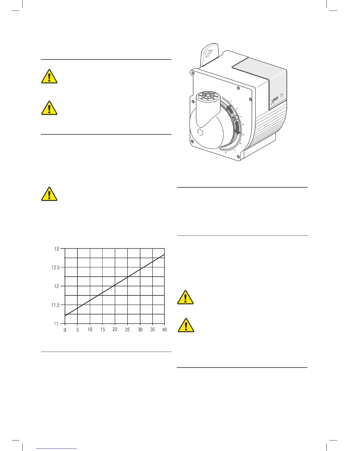
The air damper control rotates to adjust the amount of com-
bustible air (see Fig 20) and is locked in place by tightening
the air damper locking screw. (see page 22, A Fig 25 )
Air control
Clockwise = MORE air
Anti-Clockwise = LESS air
Fig. 20
8.5.1 Nozzles recommended