U Page 8
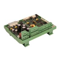
Digital controller RK 4004
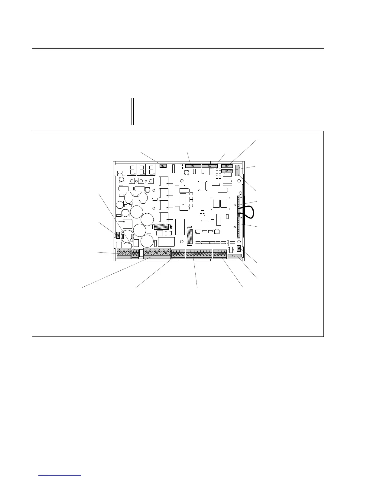
RK 40.. terminal assignments
X 9 serial bus
X 8 Analogue card
AK 4002
(only when ana-
logue sensors are
used)
X 14 External configu-
ration adapter
X 10 Optical incre-
mental encoder
X 7 CAN connection
with LED display
for CAN device
connector
X 6 Left
digital
sensor
X 5 Right
digital
sensor
X 12 CAN connection
without LED display
for internal device
networking
X 15 Fan
X 13 Supply voltage
for further E+L
modules
X 2 DC actuator
and incre-
mental en-
coder
X 3 Command sta-
tion for web
offset RE .... or
signal for path-
dependent
oscillation
X 4 Reference
switch, guider
lock and end
position signal
X 20 End switch
X 21 Supply voltage
for further E+L
modules
X 1 Operating volta-
ge
The wiring diagram indicates which connectors are assigned.
The guider lock is intended for on-site requirements where the actua-
tor is to be stopped in its current position. If the guider lock is closed
(make contact) the actuator remains in this position until the contact
is open again.
X 11 SPI bus
4. Installation
➜ Connect electrical leads according to the attached wiring diagram.
➜ Shield and run signal lines away from heavy current-carrying
leads.
The DC actuator motor line must be run separately (separate ca-
ble) from the incremental encoder line.
The connection line between the controller card and DC actuator
may be run in one lead up to a length of 3 m. From a distance of
3 m to 10 m the motor and incremental encoder lines must be
run separately.