U Page 9
Digital controller RK 4004
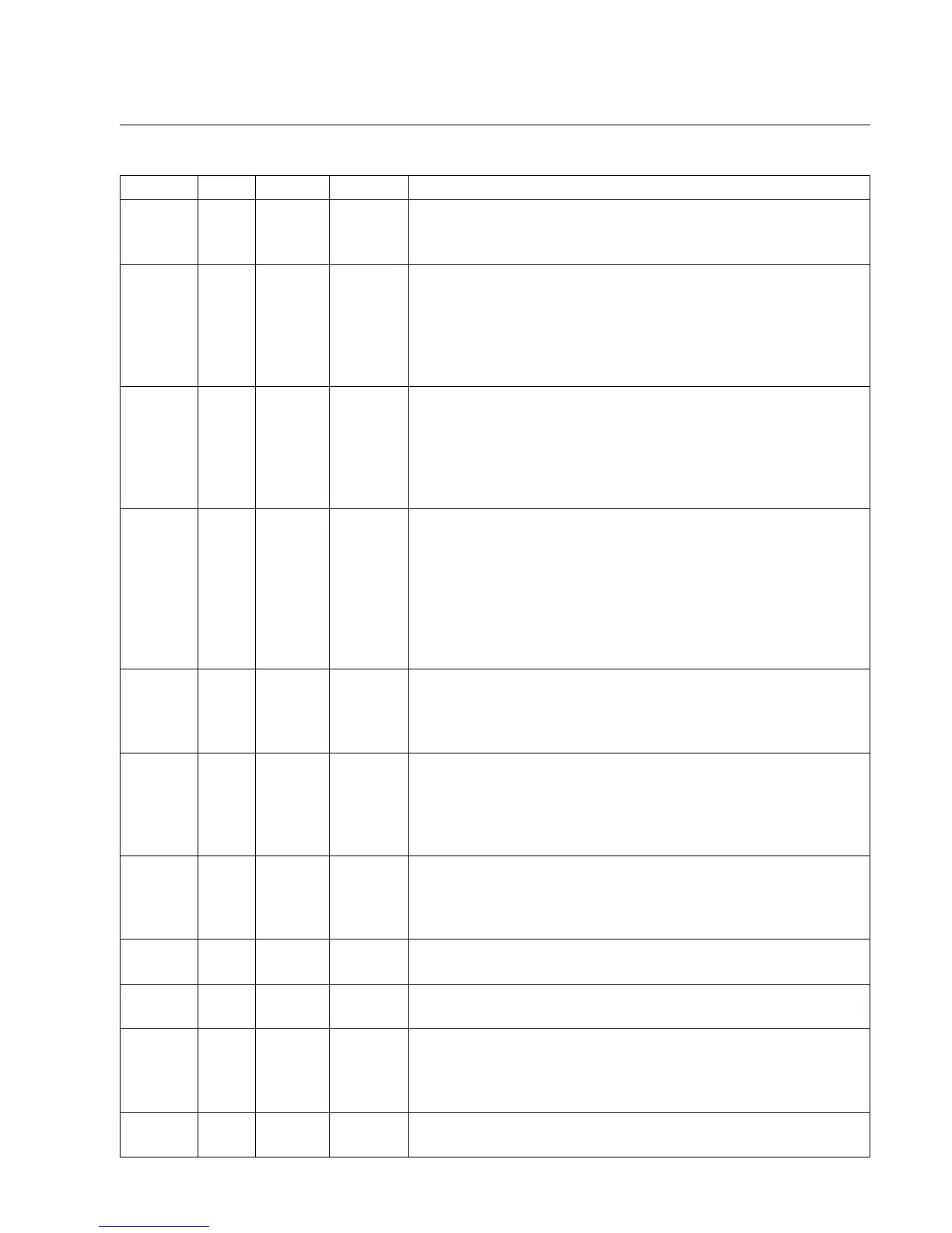
Terminal No. Input Output Assignment
X 1 1 X +24 V DC supply voltage
2X 0 V
3 X Ground
X 2 1 X DC actuator
2 X DC actuator
3 X Incremental encoder on DC actuator track A
4 X Incremental encoder on DC actuator track B
5 X +24 V DC
6X0 V
X 3 1 X +24 V DC
2 X Web offset or path-dependent or
Oscillation signal or
automatic mode signal (for minimum operation only)
3X0 V
4 X Sensor range limit
X 4 1 X Guider lock
2 X 0 V potential 0 V for controller lock
3 X +24 V DC reference switch
4 X Reference switch signal
5 X 0 V reference switch
6 X +24 V DC
7 X Actuator end position signal
8X0 V
X 7 1 X X CAN High
2 X X CAN Low
3 X LED +
4 X LED -
X 10 1 X GND (0 V)
2 X (Index) -
3X Track A
4 X +5 V
5X Track B
X 12 1 X X CAN High
2 X X CAN Low
3 - - free
4 - - free
X 13 1 X +24 V
2 X GND 0 V
X 15 1 X +12 V
2 X Switch output
X 20 1 X +24 V
2 X Actuator 2nd end position signal
3X0 V
4 X system on stand-by
X 21 1 X +24 V
2X0 V
4.1 Terminal assign-
ments X 1 to X 21