L200/L201/L100/L101 Revision A
Disassembly/Assembly Details of Disassembling/Reassembling by Parts/Unit 26
Confidential
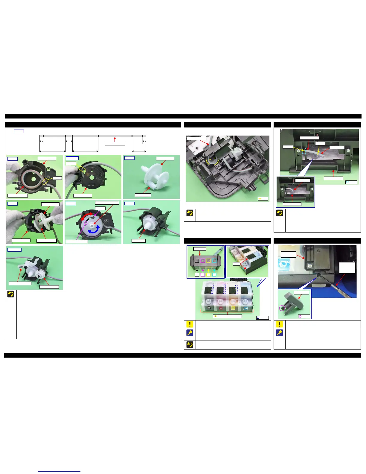
Gear Pump Idle/ Gear Pump/ Bracket Pump/ Roller Pump/ Waste Ink Tube/ Pump Housing
When reassembling the Pump Assy, follow the instructions below.
1. Make six points on the Waste Ink Tube.
2. Insert the Waste Ink Tube in the hole of the Pump Housing with the red line of the tube set as shown in the figure above.
3. Secure point C of the Waste Ink Tube to the point C of the Pump Housing.
4. Secure point D of the Waste Ink Tube to the point D of the Pump Housing.
5. Install the Roller Pump to the Bracket Pump.
6. Set the Waste Ink Tube inside the Bracket Pump, and install the Bracket Pump to the Pump Housing.
7. Rotate the Bracket Pump shaft and make sure that the Roller Pump shaft moves to both ends in the groove.
8. Make sure that point D is placed in the correct position.
9. Install the Gear Pump.
10. Install the Gear Pump Idle.
11. Install the Lever Pick Clutch.
Step 10, 11
Lever Pick Clutch
Gear Pump Idle
Step 7
Roller Pump shaft
Groove
Bracket Pump shaft
Step 6
Pump Housing
Bracket Pump
Waste Ink Tube
Pump Housing
Point D
Step 4, 8
Step 2,3
Point C
Pump Housing
Waste Ink Tube
Step 1
Waste Ink Tube
ABC D EF
10
±1 mm
110.5
±1 mm 110±1 mm 39±1 mm
10
±1 mm
19
±1 mm
Step 5
Bracket Pump
Roller Pump
Cap Unit side Waste Ink Tray Assy side
Pump Assy
Route the Ink Tube along the ribs on the Frame Base.
After installing the Ink Tube, make sure that no part of the tube
is pressed flat.
Waste Ink Tray Assy
When installing the Waste Ink Tube, pay attention to the following
instructions.
Align and secure the point E (p 26) of the Waste Ink Tube to
the hook on the Frame Base.
Insert the Holder Tube up to the point F (p 26) of the Waste Ink
Tube, and insert the holder into the Duct Tube End.
Waste Ink Tube
Point E
Point F
Holder Tube
Waste Ink Unit
Hook
Ink Supply Tank Assy
Be careful not to damage or peel off the film of the Ink Supply
Tank Assy.
To make disassembling the Ink Supply Tank Assy easier, push
slightly the part A of the Ink Supply Tank shown in the figure
above to release the hooks.
When assembling the Ink Supply Tank Assy, attach them according
to their color in the order of the indications on the Top Cover.
Valve Lever
In order to prevent ink spill, make sure to close the Valve Lever
before disassembling. (p 10)
When removing the Valve Lever, follow the instructions below.
1. Remove the Ink Supply Tank Assy from the Housing.
2. Insert the flathead precision screwdriver by the Tube Valve
Holder Rear as shown in the figure above.
3. Release the hook and remove the Valve Lever.
Flathead
precision
screwdriver
Tube Valve
Holder Rear