L120 Revision A
Disassembly/Reassembly Detailed Disassembly/Reassembly Procedure for each Part/Unit 38
Confidential
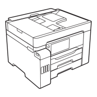
Ink Supply Tube Assy
Follow the procedure below when installing the Ink Supply Tube Assy.
1. Mark the two points on the Ink Supply Tube Assy as shown above, and put the tube clamp while aligning it with the second marking.
2. Connect the Ink Supply Tube to the Joint. (p 38)
3. Place the Ink Supply Tube Assy on the Tube Guide Sheet, and engage the both ends of the Tube Guide Sheet Sub by inserting one end (Section
A) into the hole of the other end from above.
4. Attach the Tube Pressing Plate on the Star Wheel Holder Assy, and secure it with the screw (x 1).
5. Connect the Ink Supply Tube to the Adapter, and install the Adapter to the CR Unit. (p 39)
6. Route the Ink Supply Tubes through the grooves of the CR Unit, and align the 1st markings on the Ink Supply Tubes with the edge of the grooves
as shown in the figure above.
290 ± 1 mm
160 ± 1 mm
Black
Magenta
Yellow
Cyan
Joint side
Adapter side
Ink Supply Tube Assy: Step 1
2nd marking
1st marking
Tube clamp
OK
Ink Supply
Tube
Section A
Hole
Tube Guide
Sheet Sub
Adapter
Ink Supply Tube
Align 1st markings
with edge of grooves.
CR Unit
Grooves
Step 6
NG
Ink Supply
Tube
Section A
Hole
Tube Guide
Sheet Sub
Tube Pressing Plate
Ink Supply Tube
Step 2, 4
Step 3
C.B.P-TITE SCREW 2.6x5 F/ZN-3C (2.55 ± 0.05 kg·fcm)
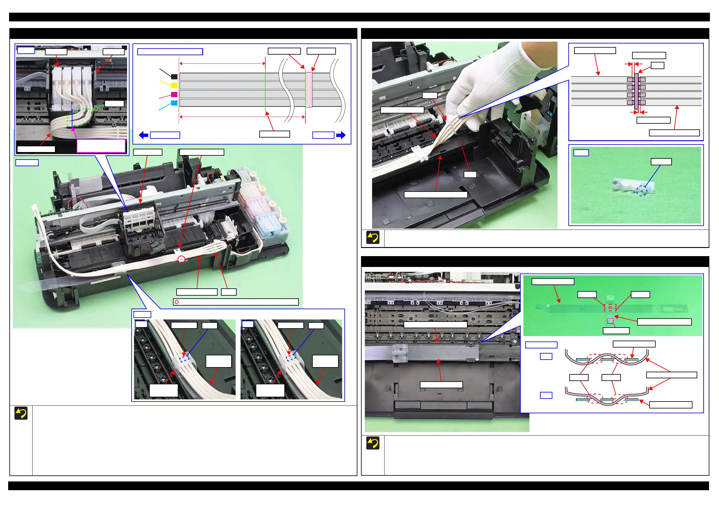
Joint
When attaching the Joint, align the cutout of the Joint with the rib of the Ink Supply Tube Guide 2nd.
Make sure the gaps between the end of Ink Supply Tank Tubes or Ink Supply Tubes and the Joint are 0.5 mm long or less.
Joint
Rib
Ink Supply Tube
Ink Supply Tube Guide 2nd
0.5 mm or less
Ink Supply Tube
Ink Supply Tank Tube
Joint
0.5 mm or less
Tube Guide Sheet / Tube Guide Sheet Sub
Refer the figure above and follow the procedure below when attaching the Tube Guide Sheet Sub to the Tube Guide Sheet.
1. Insert the section A of the Tube Guide Sheet Sub into the hole 1 of the Tube Guide Sheet from the bottom.
2. Insert the section A of the Tube Guide Sheet Sub into the hole 2 of the Tube Guide Sheet from the top.
When attaching the Tube Guide Sheet to the Ink Supply Tube Guide 2nd, while keeping the Tube Guide Sheet Sub attached on the Tube Guide
Sheet, align the holes of the Tube Guide Sheet with the protrusions of the Ink Supply Tube Guide 2nd.
Hole 2
Section A
Hole 1
Tube Guide Sheet
Tube Guide Sheet Sub
OK
Cross Section
NG
Hole 2
Tube Guide Sheet Sub
Tube Guide Sheet
Tube Guide Sheet
Hole 1
Tube Guide Sheet
Ink Supply Tube Guide 2nd

 Loading...