L350/L300/L355/L210/L110 Series Revision B
Disassembly/Reassembly Detailed Disassembly/Reassembly Procedure for each Part/Unit 45
Confidential
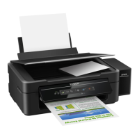
PF Grounding Spring
When installing the PF Grounding Spring, follow the procedure below.
1. From the left side of the printer, insert the spring leg A of the
PF Grounding Spring into the hole of the Frame Base.
2. Insert the spring leg B of the PF Grounding Spring into the
groove of the Frame Base.
3. Attach the spring leg B of the PF Grounding Spring to the
cutout of the Main Frame to install the PF Grounding Spring.
Insert spring leg
A into groove.
PF Grounding
Spring
Left
Main Frame
Spring leg B
Cutout
PF Grounding
Spring
Spring leg B
Spring leg A
Frame Base
Assy
Hole
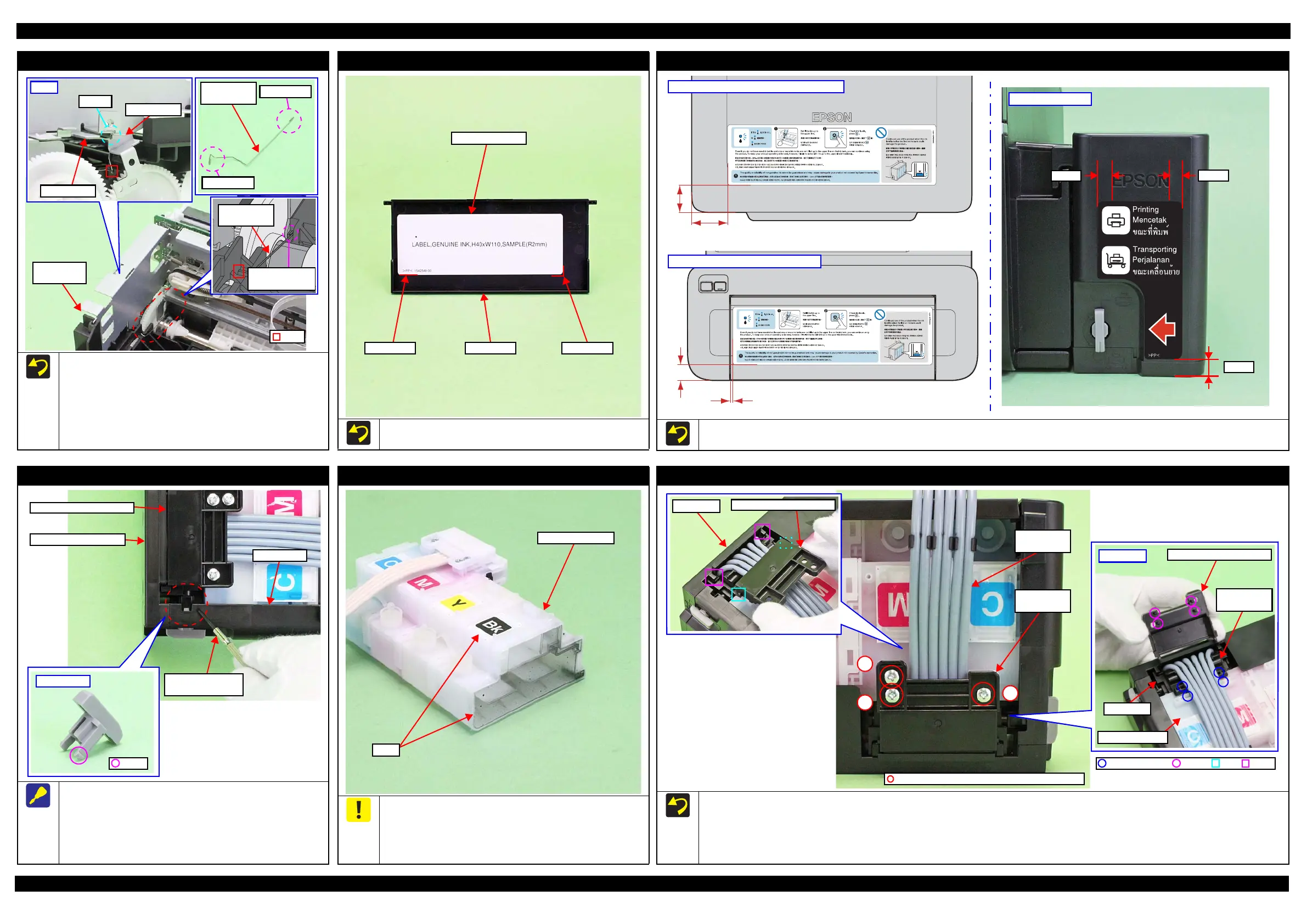
Top Cover
When attaching the Top Cover Label, align it with the markings on
the Top Cover as shown in the figure above.
Marking Marking
Top Cover Label
Top Cover
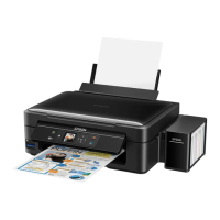
Refilling Ink Label / Valve Position Label
Attach the Refilling Ink Label and Valve Position Label according to the standards shown in the figure above.
6.4 mm
7.5 mm
7.5 mm
Valve Position Label
35.0 mm
46.2 mm
Refilling Ink Label: L350/L355/L210 Series
3.4 mm
21.0 mm
Refilling Ink Label: L300/L110 Series
Valve Lever
Follow the procedure below when removing the Valve Lever.
1. Remove the Ink Supply Tank Assy from the printer.
2. Insert a flathead precision screwdriver or the like into the gap
between the Right Cover and the Tube Valve Holder Rear to
release the hook of the Valve Lever, and then remove the
Valve Lever.
Flathead precision
screwdriver
Ink Supply Tank Assy
Right Cover
Tube Valve Holder Rear
Valve Lever
Hook
Ink Supply Tank Assy
Be careful not to damage or peel off the film of the Ink Supply
Tank.
Be careful about how to place the Ink Supply Tank Assy in
order to prevent printing failure from occurring. (See
"2.1.5Checks and Precautions before Disassembling (p25)".)
Film
Ink Supply Tank
Tube Valve Holder Front / Rear
Follow the procedure below when installing the Tube Valve Holder Rear.
1. Insert the ribs (x2) of the Tube Valve Holder Rear under the hooks (x2) of the Valve Case.
2. Align the dowels (x4) of the Tube Valve Holder Rear with the positioning holes (x2) of the Ink Supply Tank and the positioning holes (x2) of the
Tube Valve Holder Front.
3. Make sure no Ink Supply Tank Tubes are caught, then secure it with the screws (x3) in the order shown in the above figure.
1
2
3
Ink Supply
Tank Tube
Tube Valve
Holder Rear
C.B.P-TITE SCREW 3x6 F/ZN-3C (4 ± 1 kg·fcm)
Back side
Tube Valve Holder Rear
Valve Case
Ink Supply Tank
Tube Valve
Holder Front
Valve Case
Tube Valve Holder Rear
HookRibPositioning Hole Dowel

 Loading...