L365/L366,L360/L362,L310/L312,L220/L222,L130/L132 Series Revision A
Disassembly/Reassembly Detailed Disassembly/Reassembly Procedure for each Part/Unit 44
Confidential
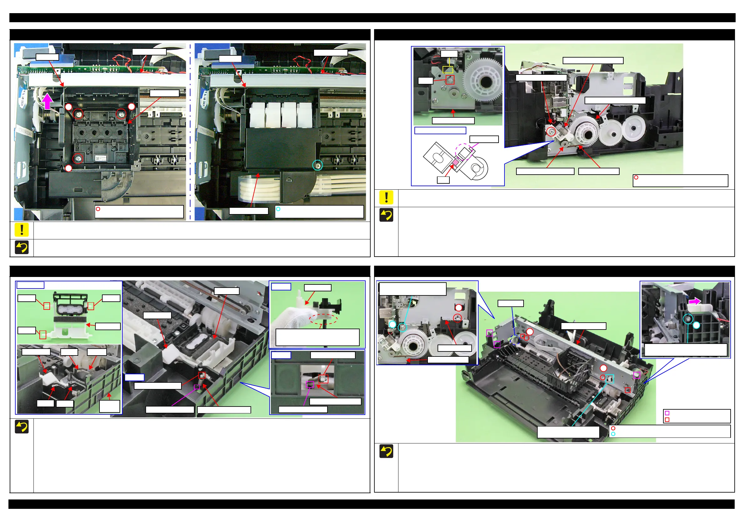
Printhead/Adapter Cover
When removing/replacing the Printhead or the Adapter Cover, not to apply excessive downward force when tightening the screws. Otherwise, the
Main Frame may be deformed by applying force perpendicularly when tightening the screws and it may affect print quality.
Tighten the screws of the Printhead in the order indicated in the figure above while pressing the Printhead in the direction of the arrow.
2
1
3
Main Frame
Printhead
CR Unit
C.B.P-TITE SCREW 2.5x8 F/ZN-3C
(5 ± 0.5 kgf·cm)
CR Unit
Main Frame
Adapter Cover
C.B.P-TITE SCREW 2.5x8 F/ZN-3C
(6 ± 1 kgf·cm)
PF Driven Pulley Assy / PF Timing Belt
Do not hold the PF Driven Pulley Assy when securing it with the screw in order to prevent applying improper tension to the PF Timing Belt.
When installing the PF Driven Pulley Assy, follow the procedure below.
1. Align the rib of the PF Driven Pulley Assy with the hook of the PF Motor Frame, and install the PF Driven Pulley Assy.
2. Attach the Compression Spring 5.07 to the protrusion of the PF Driven Pulley Assy and the dowel of the PF Motor Frame.
3. Attach the PF Timing Belt in the order of the pinion gear of the PF Motor, PF Driven Pulley and Combination Gear 29.2,42.
4. Rotate the Combination Gear 29.2,42 clockwise three times to confirm the PF Timing Belt is correctly attached, and then secure the PF Driven
Pulley Assy with the screw and washer to the PF Motor Frame.
Pinion gear of PF Motor
Hook
PF Motor Frame
Dowel
Rib
PF Driven Pulley Assy
Protrusion
Compression Spring 5.07
Combination Gear 29.2,42
PF Timing Belt
PF Driven Pulley Assy
C.B.S-TITE(P2) SCREW 3x6 F/ZN-3C
P.W. 3.4x0.43x7 (7 ± 1 kgf·cm)
Cap Lever/Cap Assy
When installing the Cap Lever/Cap Assy, follow the procedure below.
1. Attach the Cap Lever to the Frame Base, and attach one end of the Extension Spring 0.65 to the hook of the Frame Base.
2. Connect the tube of the Pump Unit to the joint on the bottom of the Cap Assy. Then, viewing from the side, confirm the marking (10
±
1 mm
from the tube end) on the tube is covered by the Cap Slider.
3. Insert the shaft A of the Cap Assy through the hole of the Cap Lever to the hole A of the Frame Base.
4. Insert the shaft B of the Cap Assy through the cutout of the Frame Base and to the hole B of the Frame Base.
5. Insert the shaft C of the Cap Assy to the hole C of the Frame Base.
6. Using a “spring hook jig” (p 17), attach the other end of the Extension Spring 0.65 to the hook of the Cap Assy.
7. Attach the Extension Spring 1.329 to the hooks of the Cap Lever and Frame Base.
Cap Lever
Extension Spring 1.329
Cap Assy
Extension Spring 0.65
Hook of Cap Assy
Hook of Frame Base
Step 6
Shaft BShaft A
Shaft C
Cap Assy
Step 2
Make sure the marking (10 ± 1 mm
from the tube end) on the annot be
seen when viewed from the side.
Cap Slider
CutoutHole BCap Lever
Frame
Base
Hole A
Hole C
Step 1, 3-5
Hook of Frame Base
Hook of Cap Lever
Step 7
Main Frame Assy
Before installing the Main Frame Assy, shift the Change Lever back to the rear.
When installing the Main Frame Assy, make sure of the following.
• The Change Lever must not interfere with the Main Frame.
• The above shown ribs and grooves, positioning holes and dowels are correctly aligned.
• The section A of the Main Frame Assy is not deformed.
Tighten the screws in the order indicated in the figure above.
3
5
Align the screw holes of Main
Frame and PF Motor Frame.
PF Motor Frame
Main Frame
4
Tighten screw while pressing Main
Frame in the direction of the arrow.
C.B.P-TITE SCREW 3x10 F/ZN-3C (6 ± 1 kgf·cm)
C.B.S-TITE SCREW 3x6 F/ZN-3C (6 ± 1 kgf·cm)
1
2
Main Frame Assy
Change Lever must not
interfere with Main Frame.
Rib and groove
Positioning hole and dowel
Section A
 Loading...