Page-13
The output levels of the STD.P pin are low (down) and open circuit (up).
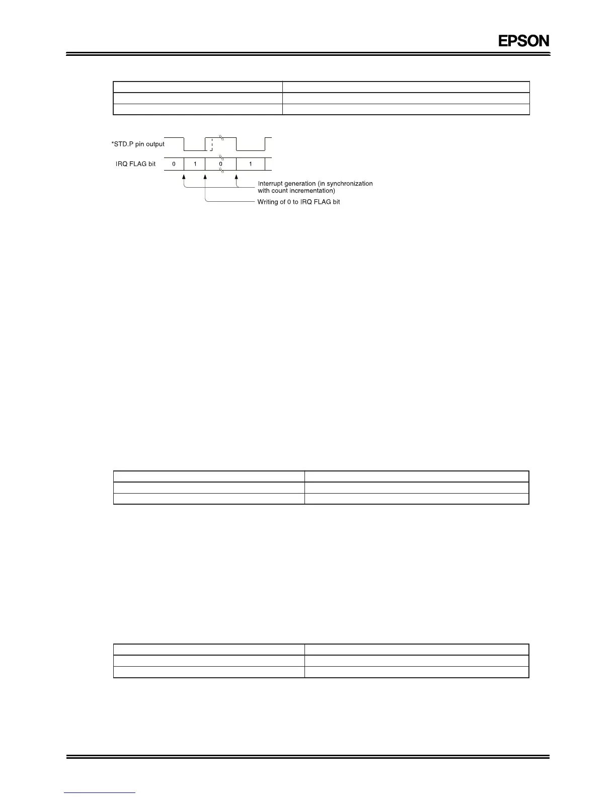
Note: If the STD.P pin output remains low as set, subsequently generated interrupts are ignored. In order to prevent
interrupts from being overlooked, write 0 to the IRQ FLAG bit before the next interrupt is generated, to return
the STD.P pin to high.
iii.Initial setting of IRQ FLAG bit
If the fixed-period interrupt mode is not used, set the IRQ FLAG bit to 1. If the fixed-period interrupt mode is used,
set the IRQ FLAG bit to 0.
(4) 30-second ADJ bit (D
3)
The 30-seconds ADJ bit provides a 30-seconds correction (by which term is meant a rounding to the nearest whole
minute) when 1 is written to it. The 30-seconds correction takes a maximum of 76.3 mseconds to perform, and after the
correction the 30-seconds ADJ bit is automatically returned to 0. This operation also clears the sub-second bits of the
internal counter down to the 1/256-seconds counter. During the 30-seconds correction, access to the counter registers
at addresses 0 to C is inhibited, so monitor the 30-seconds ADJ bit to check that this bit has returned to 0, before
starting subsequent processing. If no access is made to the RTC for 76.3 mseconds or more after 1 is written to the 30-
seconds ADJ bit, there is no need to check the 30-seconds ADJ bit again.
i. Operation of 30-seconds ADJ bit
Writing 1 to the 30-seconds ADJ bit performs a 30-second correction. This 30-seconds correction changes the
seconds and minutes digits as shown below. If the minutes digits have been incremented, an upward carry is
propagated.
Example: The correction caused by the 30-seconds ADJ bit sets the time within the RTC to 00:00:00 if it was within
the range of 00:00:00 to 00:00:29, or to 00:01:00 if it was within the range of 00:00:30 to 00:00:59.
ii. Access inhibited after 30-seconds correction
For 76.3 mseconds after 1 is written to the 30-seconds ADJ bit, the RTC is engaged in internal processing, so read
to and write from the S
1 to W registers is inhibited. The 30-seconds ADJ bit is automatically cleared to 0 at the end
of the 76.3 mseconds.
3. CE register (control register E)
(1) MASK bit (D0)
The MASK bit controls the STD.P pin output. The relationships between the MASK bit, ITRPT/STND bit, and STD.P pin
output are as follows:
The timings of the MASK bit, ITRPT/STND bit, and STD.P pin output are as follows: