Page-14
RTC-72421/72423
(2) ITRPT/STND bit (D1)
The ITRPT/STND bit specifies fixed-period pulse output mode or fixed-period interrupt mode for the fixed-period
operating mode.
The mode selected by each setting of this bit is as follows:
For details of the timing of fixed-period operation, see the section on the t
0 and t1 bits below.
(3) t
0 (D2), t1 (D3) bits
These bits select the timing of fixed-period operation in fixed-period pulse output mode or fixed-period interrupt mode.
There is no special counter within the RTC for fixed-period operation; the fixed-period operation is performed at the
incrementation of the time (period) specified by the t
0 and t1 bits.
i. Setting t
0 and t1
Setting these bits specifies the generation timing for fixed-period pulse output or fixed-period interrupts.
ii. STD.P pin output control
The timing of STD.P pin output is at the incrementation of the period specified by the t
0 and t1 bits.
t
1
t
0
)ycneuqerf(doirePskrameR
00 )zH46(dnoces46/1
tuptuonipP.DTSeht,edomtuptuoeslupdoirep-dexifnI
sm5218.7rofwolsi
)sm5218.7sidoirepdnoces-46/1ehtflahtahteton(
01 )zH1(dnoces1
10 )zH06/1(etunim1
11 )zH0063/1(ruoh1
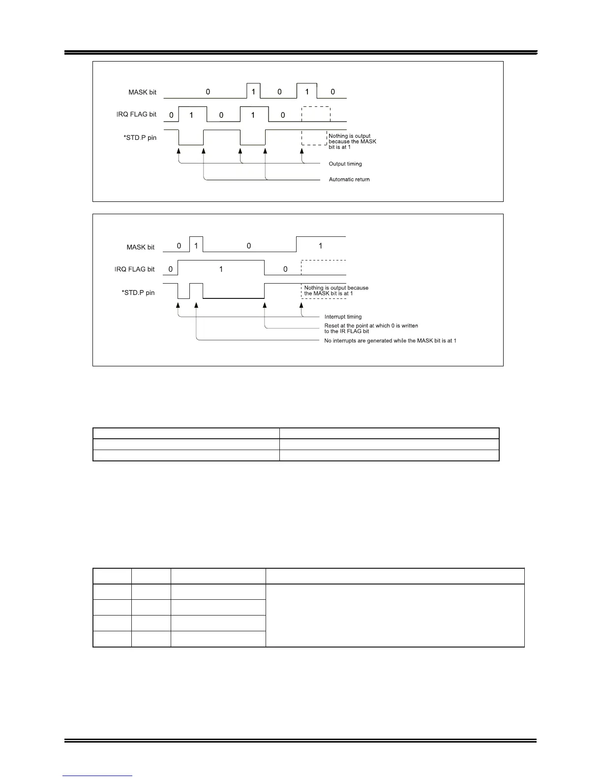
1. Fixed-period pulse output mode (ITRPT/STND=0)
The output levels of the STD.P pin are low (down) and open circuit (up).
2. Fixed-period interrupt mode (ITRPT/STND=1)
The output levels of the STD.P pin are low (down) and open circuit (up).