Page-19
4. Using the CS1 pin
The RTC-72421/RTC-72423 has 2 chip-select signal systems: CS0 and CS1. Use CS0 as chip-select for ordinary bus
access. CS
1 is not only used for CPU bus control, it also has the main function of switching between standby mode and
operating mode.
(1) Functions
Providing the CS
1 pin with the rated voltage levels enables CS1 to have the following functions:
● Enabling interface with microprocessor during operation within the operating voltage range (5.0 V
±
0.5 V)
● Reducing current consumption during standby (to prevent through currents caused by unstable inputs, which is
inherent to C-MOS devices)
● Protecting internal data during standby
To ensure these functions, make sure that operation of the CS
1 pins observes that following conditions:
● Make sure that the voltage input to the CS
1 pin during operation is at least 4/5 VDD.
● Make sure that the voltage input to the CS
1 pin during standby is as close as possible to 0 V, to prevent through
currents.
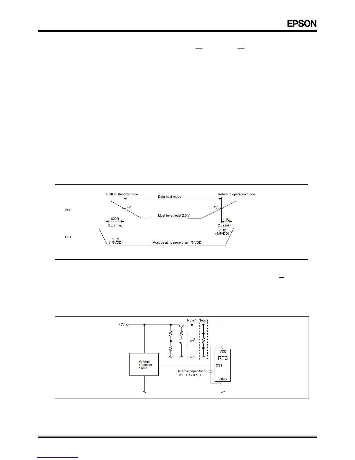
● Make sure that the operation conforms to the timing chart below during a shift to standby mode or a return to
operating mode.
* Standby mode is a state in which a voltage lower than the RTC's rated range of operating supply voltage is applied
(4.5 V to 2.0 V). Under this condition, the timer continues to operate under battery back-up power, but the interface
between the interior and exterior of the RTC cannot be guaranteed.
(2) Timing
(3) Note
If the RTC is operated with timing conditions different from those shown above, data within the RTC could be
overwritten during a shift to standby mode or a return to operating mode. For example, if a write signal (
WR) is generated
during either of the timing conditions (t
CDR, tR) shown in the timing chart above, the data will be input before the RTC
has stabilized. To ensure that data is held throughout the entire standby process, make sure that the timing conditions
shown in the chart are followed.
■ Power supply circuit example
Note 1: This capacitor must be of a high capacity because a transient reverse current flows from the collector to the
emitter of the transistor when the power is turned off.
Note 2: Use a chargeable or lithium battery. If a chargeable battery is used, there is no need for the diode. If a lithium
battery is used, the diode is necessary. For specific details of the resistance of the resistor, contact the
manufacturer of the battery that is used.
Do not access the RTC while the voltage at CS1 is changing.