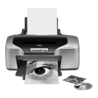
EPSON Stylus Photo R800 Revision A
DISASSEMBLY & ASSEMBLY Disassembly 77
4.2 Disassembly
A disassembling flowchart is shown below. When disassembling any unit, refer to the page number shown in the following flowchart.
Figure 4-1. Disassembling Procedure Flowchart
"CR Scale"
4.2.6.3 Page 99
"CSIC Board"
4.2.6.6 Page 111
"Cover Open
Sensor Holder"
4.2.8.1 Page 133
"Print Head"
4.2.6.2 Page 97
"APG Assy."
4.2.6.4 Page 101
"Paper EJ Frame
Assy."
4.2.6.8 Page 116
"CR Motor"
4.2.7.1 Page 130
"Lower Housing/
Printer Mechanism"
4.2.1.3 Page 80
"ASF Assy."
4.2.4 Page 86
"Panel Board"
4.2.5.3 Page 94
"PF Encoder
Sensor Holder"
4.2.8.6 Page 138
"PS Board"
4.2.5.2 Page 93
"Upper Housing"
4.2.1.2 Page 78
"Main Board"
4.2.5.1 Page 90
"Rear Housing"
4.2.1.1 Page 78
"PG Release
Sensor"
4.2.8.2 Page 134
"Stacker Assy."
4.2.2 Page 82
"PF Motor"
4.2.7.2 Page 131
"CR Scale"
4.2.6.3 Page 99
"ASF Assy."
4.2.4 Page 86
"ASF Assy."
4.2.4 Page 86
"PE Sensor
Holder"
4.2.8.3 Page 135
"Waste Ink Pads"
4.2.3 Page 84
"APG Assy."
4.2.6.4 Page 101
"FLAG Release
Assy."
4.2.6.9 Page 117
"Ink System Unit"
4.2.6.7 Page 114
"Carriage Shaft/
Carriage Unit"
4.2.6.5 Page 103
"Upper Paper
Guide Assys."
4.2.6.10 Page 119
"Stacker Assy."
4.2.2 Page 82
"Paper EJ Frame
Assy."
4.2.6.8 Page 116
"CR Encoder
Board"
4.2.8.5 Page 137
"Ink Mark Sensor/
PW Sensor"
4.2.8.4 Page 136
"Front Paper
Guide"
4.2.6.11 Page 120
"Front Paper EJ
Roller Assy."
4.2.6.13 Page 124
"PF Encoder
Sensor Holder"
4.2.8.6 Page 138
"Rear Paper EJ
Roller Assy."
4.2.6.12 Page 123
"PF Roller"
4.2.6.14 Page 127
START
"ASF Assy."
4.2.4 Page 86
"Carriage Shaft/
Carriage Unit"
4.2.6.5 Page 103
"Ink System Unit"
4.2.6.7 Page 114
* The step for the unit or discrete part within
the broken line is not the shortest removal
step but is the step necessary for
removing the next unit or discrete part.
Download Service Manual And Resetter Printer at http://printer1.blogspot.com

 Loading...


