Do you have a question about the Epson T3-401S and is the answer not in the manual?
Guidelines for safe design and installation of robot systems.
Key considerations for designing safe and effective robot systems.
Essential safety precautions for operators during robot system operation.
Description of the different operating modes available for the robot system.
Safety precautions and guidelines for performing maintenance on the robot system.
Procedures and components related to emergency stopping of the robot system.
Overview of safety features like Emergency Stop Switch and Safety Door Input.
Procedures and precautions for installing the robot manipulator.
Essential safety steps before and during manipulator installation.
Step-by-step guide for installing the robot manipulator securely.
Instructions for connecting safety devices to the EMERGENCY connector.
Details on connecting safety door and latch release switches.
Functionality and connection of the safety door interlock switch.
Functionality and connection of the latch release switch.
Requirements for external emergency stop switches and their connection.
Procedure to verify the proper functioning of the emergency stop switch.
Detailed pin assignments for the EMERGENCY connector.
Illustrative circuit diagrams for emergency stop and safety door connections.
Requirements for power supply, cables, and circuit breakers.
Instructions for installing the EPSON RC+ 7.0 software on a development PC.
Steps for connecting the development PC to the robot manipulator.
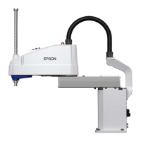
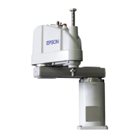
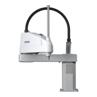
| Robot Type | SCARA |
|---|---|
| Number of Axes | 4 |
| Maximum Payload | 3 kg |
| Reach | 400 mm |
| Repeatability | ±0.01 mm |
| Degrees of Freedom | 4 |
| Mounting Orientation | Wall, Ceiling |
