Do you have a question about the Epson G10 Series and is the answer not in the manual?
Describes compatible controller and software combinations for the robot system.
Instructions on properly powering the robot system components on and off.
Notes that motor shapes may vary based on manipulator specifications.
Indicates that setting procedures using software are marked with a specific icon.
Explains safety symbols (Warning, Caution) and their meanings.
Safety precautions for personnel designing and installing the robot system.
Safety guidelines for qualified operators to follow during robot system operation.
Procedure for using the emergency stop and information on free running distance.
How to manually move robot joints and arms in emergency mode.
Identifies safety labels attached to the manipulator and their meanings.
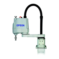
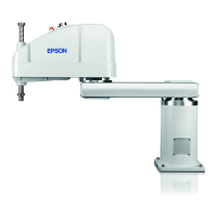
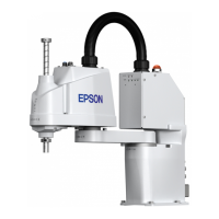
Highlights key features and advantages of the G10 and G20 manipulator series.
Explains the model number nomenclature and differences between variants.
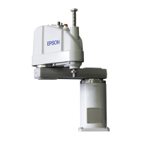
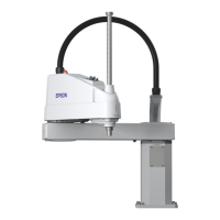
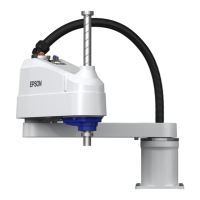
Identification of manipulator parts and their overall external dimensions.
Details the parts and dimensions for the table-top mounting configuration.
Illustrates additional parts and specifications for Cleanroom models.
Details the parts and dimensions for the wall-mounting configuration.
Shows additional parts for wall-mounted Cleanroom models.
Details the parts and dimensions for the ceiling-mounting configuration.
Illustrates additional parts for ceiling-mounted Cleanroom models.
Comprehensive table of technical specifications for G10 and G20 manipulators.
Specifies required ambient conditions for optimal and safe manipulator operation.
Requirements for the base table used for anchoring the manipulator.
Detailed dimensional information for table top, wall, and ceiling mounting.
Instructions and precautions for safely unpacking and transporting the manipulator.
Important safety warnings for handling and moving the manipulator during transport.
Step-by-step guide for installing the standard manipulator in different mounting configurations.
Detailed steps for installing the manipulator using the table top mounting method.
Detailed steps for installing the manipulator using the wall mounting method.
Detailed steps for installing the manipulator using the ceiling mounting method.
Specific installation steps for cleanroom-compatible manipulator models.
Instructions for properly connecting power and signal cables to the manipulator and controller.
Information on user electrical wires, pneumatic tubes, and their connectors.
Guidelines and safety precautions for moving and storing the manipulator.
Safety warnings for handling and securing the manipulator during relocation or storage.
Steps and precautions for relocating/storing the manipulator in table top configuration.
Steps and precautions for relocating/storing the manipulator in wall configuration.
Steps and precautions for relocating/storing the manipulator in ceiling configuration.
Guidelines for attaching end effectors, including shaft and brake release button operation.
Information on using threaded holes on Arm #2 for attaching cameras and valves.
How to set weight and inertia parameters for optimal manipulator performance.
Procedure for setting manipulator weight parameters based on load capacity.
Calculating equivalent weight for attached equipment and entering it into the weight parameter.
Procedure for setting manipulator inertia parameters for optimal performance.
Setting the moment of inertia parameter and its effect on acceleration/deceleration.
Setting eccentric quantity parameter and its impact on manipulator performance.
Setting the eccentric quantity parameter and its effect on acceleration/deceleration.
Examples of formulas for calculating the moment of inertia of various load shapes.
Precautions for adjusting acceleration/deceleration based on Joint #3 position.
Setting motion range using pulse values for all joints.
Setting the maximum pulse range for Joint #1.
Setting the maximum pulse range for Joint #2.
Setting the maximum pulse range for Joint #3.
Setting the maximum pulse range for Joint #4.
Physically limiting manipulator motion range using mechanical stops.
How to set mechanical stops for Joints #1 and #2 using bolts.
Details for setting mechanical stops for Joint #2 across different mounting types.
Procedure for setting the lower limit mechanical stop for Joint #3.
Setting software-based limits for X and Y coordinates for Joints #1 and #2.
Diagrams and values for the default maximum motion range of the manipulator.
Lists parts categorized by standard and cleanroom environment models.
