Setup & Operation 5. Motion Range
62 G10 / G20 Rev.2
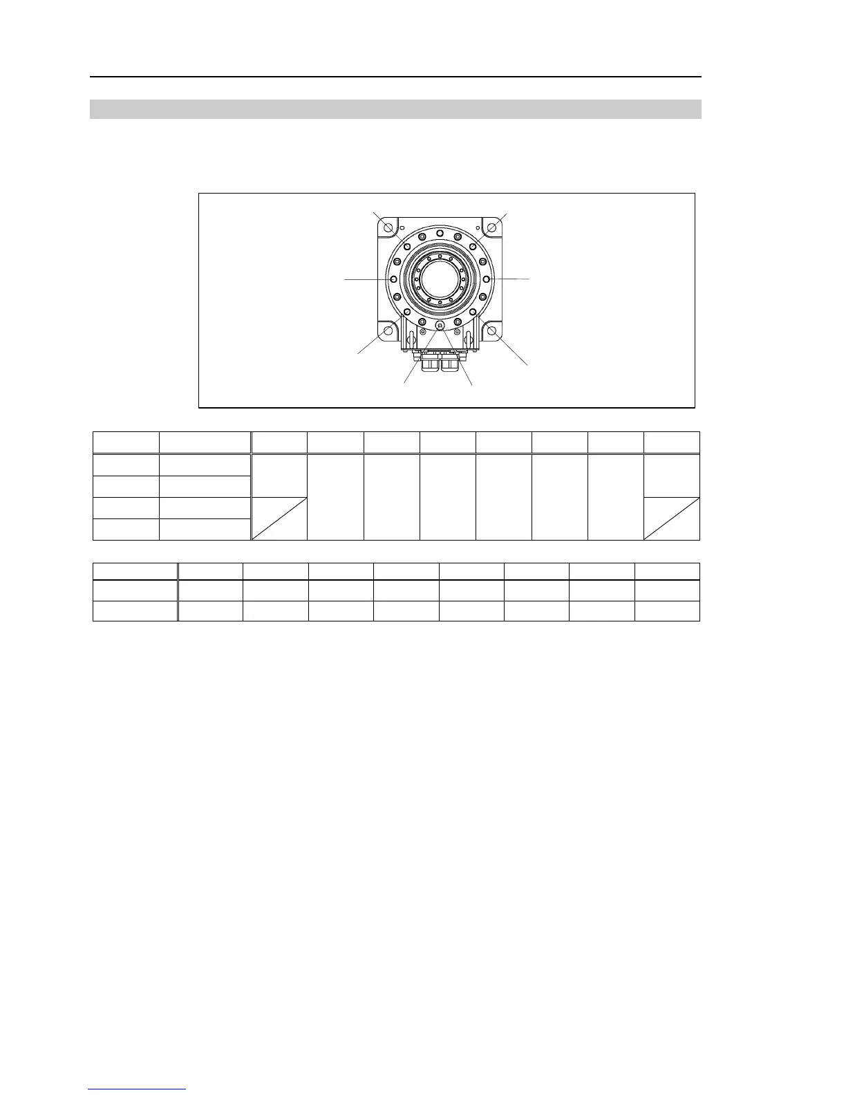
5.2.1 Setting the Mechanical Stops of Joints #1 and #2
Both Joints #1 and #2 have threaded holes in the positions corresponding to the angle for
the mechanical stop settings. Install the bolts in the holes corresponding to the angle that
you want to set.
a
b
c
d
e
f
g
h
Joint #1 Mechanical Stops
Joint #1
Mounting Arm Length
a b c d e f g h
Table Top
65/85/A0
Ceiling
85/A0
+152°
-152°
Ceiling
65
Wall
65/85/A0
+107° +60° +15°
-15°
-60° -107°
a b c d e f g h
Setting Angle
+152°
+107° +60° +15°
-15°
-60° -107° -152°
Pulse Value
+7048761
+5738041 +4369067 +3058347 +2184534 +873814
-495161
-1805881
(°: degree)
 Loading...


