FLANGE ALIGNMENT TOOLS
OPERATOR INSTRUCTION MANUAL
PAGE 6
4. FLANGE MISALIGNMENT DETERMINATION PROCEDURE
The tool being used must not be attached to a anged joint prior to the misalignment
procedure being carried out.
4.1 LATERAL MISALIGNMENT
1. Loosen and remove every second bolt around the ange , continue with this until
misalignment occurs.
A anged joint, once broken down, may spring out of alignment at any point, or in
any direction around its circumference. Misalignment may not occur until only a few
bolts remain.
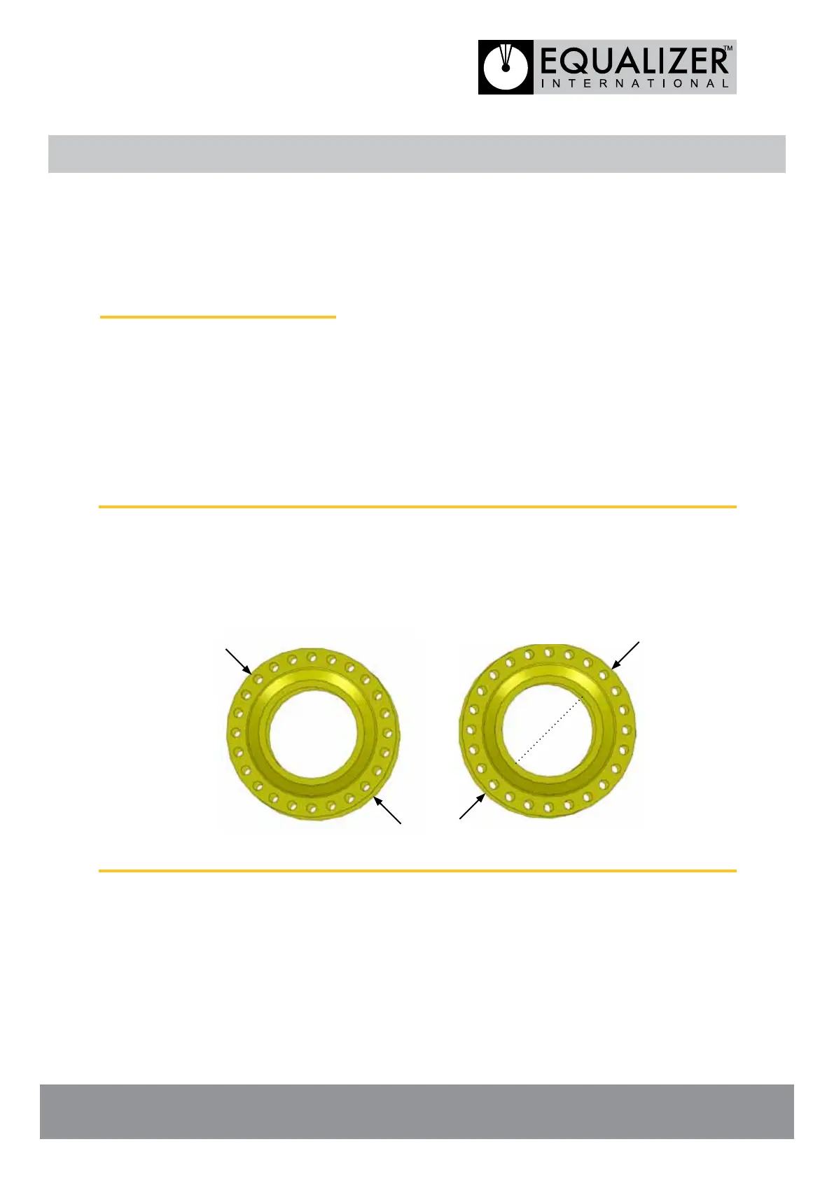
2. At this point the direction of any misalignment should become obvious. The
alignment tool being used should be attached at the maximum point of misalignment
(point A or B in the examples shown below).
POINT A
POINT B POINT A
POINT B