FLANGE ALIGNMENT TOOLS
OPERATOR INSTRUCTION MANUAL
PAGE 20
6.3 INSTALLATION AND OPERATION
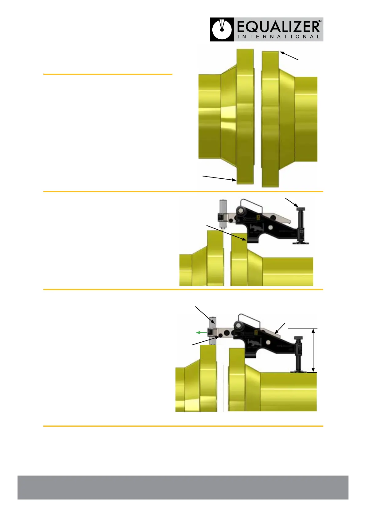
1. Carry out the Flange Misalignment
Determination Procedure (see
section 4) to determine the points
of maximum misalignment.
In this example the points of
maximum misalignment are at the
top and bottom of the joint.
2. Guide the lift hook into the bolt-hole
at the maximum point of
misalignment.
Adjust the drop leg onto the pipe
(using the adjusting knob) while
holding the lift hook up level with
the bolt-hole.
3. Loosen the wing release knob and
extend the wing out to the required
distance.
Rotate the hydraulic cylinder down
until the base of the cylinder
locates onto the surface of the
opposite ange.
Ensure that the tool is sitting
level and that the cylinder is
in full and even contact with the
surface of the opposite ange.
N.B. Ensure tool is parallel to pipe.
POINT OF MAX.
MISALIGNMENT
POINT OF MAX.
MISALIGNMENT
LIFT
HOOK
ADJUSTING
KNOB
WING
HYDRAULIC
CYLINDER
PARALLEL
Wing Release
Knob